METER / GAUGE SYSTEM Engine Coolant Temperature Receiver Gauge Malfunction
DESCRIPTION
In this circuit, the combination meter assembly receives engine coolant temperature signals from the ECM via the CAN communication system. The combination meter assembly displays the engine coolant temperature that is calculated based on the data received from the ECM.
WIRING DIAGRAM
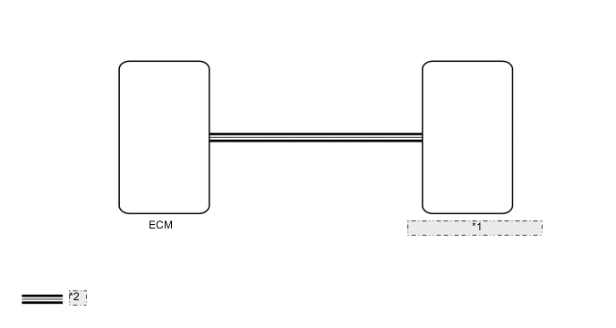
| *1 | Combination Meter Assembly |
| *2 | CAN Communication Line |
CAUTION / NOTICE / HINT
Note
-
When replacing the combination meter assembly, make sure to replace it with a new one.
-
If there is an open or short in the engine coolant temperature sensor circuit, the ECM stores DTCs. Troubleshoot the SFI system.
w/ EGR System: Click here
w/o EGR System: Click here
w/ Canister Pump Module: Click here
PROCEDURE
-
CHECK FOR DTC (CAN COMMUNICATION SYSTEM)
-
Check if CAN communication DTCs are output.
OK CAN communication DTCs are not output. Result Proceed to OK NG
NG 
GO TO CAN COMMUNICATION SYSTEM Click here
OK 
-
-
CHECK FOR DTC (SFI SYSTEM)
-
Check for DTCs.
w/ EGR System: Click here
w/o EGR System: Click here
w/ Canister Pump Module: Click here
Powertrain > Engine and ECT > Trouble CodesOK No DTCs are output. Result Result Proceed to OK A NG (w/ EGR System) B NG (w/ EGR System) C NG (w/ Canister Pump Module) D
B
GO TO SFI SYSTEM Click here
C
GO TO SFI SYSTEM Click here
D
GO TO SFI SYSTEM Click here
A
-
-
PERFORM ACTIVE TEST USING GTS (WATER TEMPERATURE METER OPERATION)
-
Using the GTS, perform the Active Test.
Body Electrical > Combination Meter > Active TestTester Display Measurement Item Control Range Diagnostic Note Water Temperature Meter Operation Engine coolant temperature receiver gauge OFF, LOW, NORMAL, HIGH -
Body Electrical > Combination Meter > Active TestTester Display Water Temperature Meter Operation OK Engine coolant temperature receiver gauge indication is normal. Result Proceed to OK NG
NG
REPLACE COMBINATION METER ASSEMBLY Click here
OK
-
-
READ VALUE USING GTS (COOLANT TEMP, COOLANT TEMPERATURE)
-
Using the GTS, read the Data List.
Powertrain > Engine and ECT > Data ListTester Display Measurement Item Range Normal Condition Diagnostic Note Coolant Temp Engine coolant temperature Min.: -40°C (-40°F), Max: 215°C (419°F) 75 to 100°C (167 to 212°F): After warming up engine -
Body Electrical > Combination Meter > Data ListTester Display Measurement Item Range Normal Condition Diagnostic Note Coolant Temperature Engine coolant temperature Min.: 0°C (0°F), Max.: 127.5°C (261.5°F) 75 to 100°C (167 to 212°F): After warming up engine -
Powertrain > Engine and ECT > Data ListTester Display Coolant Temp
Body Electrical > Combination Meter > Data ListTester Display Coolant Temperature Tech Tips
-
When the Data List values of the ECUs match, an internal malfunction of the ECM is suspected.
-
When the Data List values of the ECUs do not match, a signal output error of the ECM or an internal malfunction of the combination meter assembly is suspected.
OK The Data List values of the ECUs do not match. Result Proceed to OK NG -
NG
REPLACE ECM Click here
OK
-
-
CHECK COMBINATION METER ASSEMBLY
-
Replace the combination meter assembly.
-
Check that the operation of the engine coolant temperature receiver gauge returns to normal.
OK The operation of the engine coolant temperature receiver gauge returns to normal. Result Proceed to OK NG
OK
END (COMBINATION METER ASSEMBLY IS DEFECTIVE)
NG
REPLACE ECM Click here
-