METER / GAUGE SYSTEM, Diagnostic DTC:B150B
| DTC Code | DTC Name |
|---|---|
| B150B | Lost Communication with Gigabit Video Interface |
DESCRIPTION
The combination meter assembly receives an image information signal from the radio receiver assembly through a video signal (digital) line.
Based on this signal, audio and visual system or navigation system information is displayed on the multi-information display.
This DTC is stored when the combination meter assembly cannot receive the signal.
| DTC No. | Detection Item | DTC Detection Condition | Trouble Area |
|---|---|---|---|
| B150B | Lost Communication with Gigabit Video Interface | After the combination meter assembly receives a registration information signal, which is sent by the radio receiver assembly when the power switch is on (ACC), 1 or more times, and reception of the "Image ON" signal is confirmed, a GVIF video signal cannot be received for 1 second or more. |
|
WIRING DIAGRAM
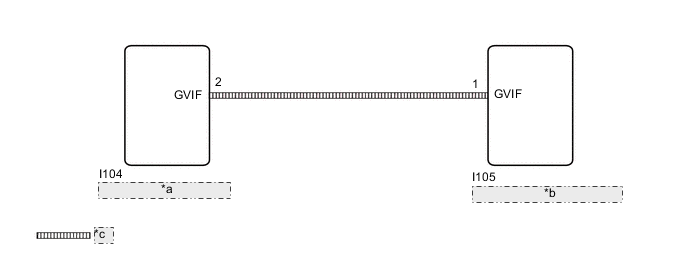
| *a | Radio Receiver Assembly |
| *b | Combination Meter Assembly |
| *c | GVIF Cable |
CAUTION / NOTICE / HINT
-
*1: w/ Navigation System
*2: w/ Audio and Visual System (except 8 Speakers)
Note
-
When replacing the combination meter assembly, make sure to replace it with a new one.
-
If DTCs B150B and B150A are output simultaneously, troubleshoot for B150A first.
-
Depending on the parts that are replaced during vehicle inspection or maintenance, performing initialization, registration or calibration may be needed. Refer to Precaution for navigation system*1 or audio and visual system*2.
w/ Navigation System: Click here
w/ Audio and Visual System (except 8 Speakers): Click here
PROCEDURE
-
CHECK FOR DTC (NAVIGATION SYSTEM, AUDIO AND VISUAL SYSTEM)
-
Check for DTCs.
w/ Navigation System: Click here
w/ Audio and Visual System (except 8 Speakers): Click here
Body Electrical > Navigation System > Trouble CodesOK DTCs are not output. Result Result Proceed to OK A NG (w/ Navigation System) B NG (w/ Audio and Visual System [except 8 Speakers]) C
B 
GO TO NAVIGATION SYSTEM Click here
C
GO TO AUDIO AND VISUAL SYSTEM Click here
A 
-
-
CHECK HARNESS AND CONNECTOR (GVIF CABLE)
-
Replace the harness and connector (GVIF cable) with a new or normally functioning one.
-
Turn the power switch on (IG) and wait 30 seconds.
Note
A maximum of 30 seconds is required to send/receive the registration information between the combination meter assembly and radio receiver assembly.
-
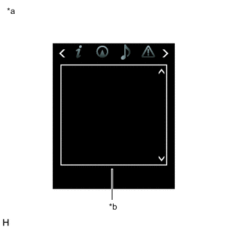
*a Multi-information Display *b Screen Operate the steering pad switch assembly and check that the audio tab illuminates.
-
Check for DTCs and check the display status of the multi-information display.
Body Electrical > Combination Meter > Trouble CodesOK The audio information illuminates and DTC B150B is not output. Result Proceed to OK NG
OK
END (GVIF CABLE IS DEFECTIVE)
NG
-
-
CHECK COMBINATION METER ASSEMBLY
-
Replace the combination meter assembly.
-
Turn the power switch on (IG) and wait 30 seconds.
Note
A maximum of 30 seconds is required to send/receive the registration information between the combination meter assembly and radio receiver assembly.
-
*a Multi-information Display *b Screen Operate the steering pad switch assembly and check that the audio tab illuminates.
-
Check for DTCs and check the display status of the multi-information display.
Body Electrical > Combination Meter > Trouble CodesOK The audio information illuminates and DTC B150B is not output. Result Proceed to OK NG
OK
END (COMBINATION METER ASSEMBLY IS DEFECTIVE)
NG
REPLACE RADIO RECEIVER ASSEMBLY Click here
-