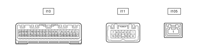
METER / GAUGE SYSTEM TERMINALS OF ECU
-
COMBINATION METER ASSEMBLY
-
Measure the voltage, resistance and waveform according to the value(s) in the table below.
Terminal No. (Symbol) Wiring Color Terminal Description Condition Specified Condition I10-2 (MSM+) - Body ground L - Body ground Steering pad switch assembly signal Power switch on (IG), enter, top and back switches on steering pad switch assembly not pushed 4.8 to 5.2 V Power switch on (IG), enter, top or back switches on steering pad switch assembly pushed Below 1 V I10-3 (MSTI) - Body ground B - Body ground Steering pad switch assembly signal Power switch on (IG), up, down, right, and left switches on steering pad switch assembly not pushed 4.8 to 5.2 V Power switch on (IG), up, down, right, or left switches on steering pad switch assembly pushed Below 1 V I10-4 (ODO) - Body ground G - Body ground ODO/TRIP switch signal Power switch on (IG), ODO/TRIP switch not pushed 4 to 6 V Power switch on (IG), ODO/TRIP switch pushed Below 1 V I10-5 (EPB) - Body ground R - Body ground Parking brake switch signal Power switch on (IG), parking brake switch is off 11 to 14 V Power switch on (IG), parking brake switch is on Below 1.5 V I10-6 (P/SB) - Body ground*6 L - Body ground Front passenger seat belt buckle switch signal Power switch on (IG), front passenger side seat occupied, front passenger seat belt unfastened Below 1 V Power switch on (IG), front passenger side seat occupied, front passenger seat belt fastened 11 to 14 V I10-9 (S) - Body ground LG - Body ground Engine oil pressure switch signal "Low Oil Pressure Stop in a Safe Place See Owner's Manual" is displayed Below 1 V "Low Oil Pressure Stop in a Safe Place See Owner's Manual" is not displayed 11 to 14 V I10-15 (OILW) - Body ground B - Body ground Ground Always Below 1 Ω I10-16 (WLVL) - Body ground*5 LG - Body ground Washer fluid level signal Power switch on (IG), washer fluid level not low 11 to 14 V Power switch on (IG), washer fluid level low Below 1 V I10-19 (+S) - Body ground V - Body ground Speed signal for other system (Output) Driving at approximately 20 km/h (12 mph) Pulse generation (See waveform 1) I10-20 (SI) - Body ground V - Body ground Speed signal for other system (Input) Driving at approximately 20 km/h (12 mph) Pulse generation (See waveform 1) I10-21 (IG+) - Body ground B - Body ground Power switch signal Power switch off Below 1 V Power switch on (IG) 11 to 14 V I10-22 (B) - Body ground Y - Body ground Battery Power switch off 11 to 14 V I10-25 (TR) - Body ground V - Body ground Trip switch signal Power switch on (IG), up switch and down switch of trip switch not pushed 4.6 to 5.3 V Power switch on (IG), up switch of trip switch pushed Below 1 V Power switch on (IG), down switch of trip switch pushed 2 to 3.6 V I10-26 (SW3) - Body ground P - Body ground Trip switch signal Always Below 1 V I10-27 (FR) - I10-28 (FE) SB - GR Fuel sender gauge signal Power switch on (IG), fuel level F Below 1 V Power switch on (IG), fuel level E 4.5 to 9 V I10-29 (CANH) - Body ground G - Body ground CAN communication line - - I10-30 (CANL) - Body ground W - Body ground CAN communication line - - I10-31 (ES) - Body ground W-B - Body ground Ground Always Below 1 Ω I10-32 (TX-) - Body ground*1 R - Body ground Headup display communication signal Power switch on (IG) Pulse generation (See waveform 2) I10-33 (CS) - Body ground*1 Y - Body ground Headup display communication signal Power switch on (IG) Pulse generation (See waveform 3) I10-38 (INT) - Body ground*2 LG - Body ground Tire pressure warning reset switch Power switch on (IG), tire pressure warning reset switch off 8 to 15 V Power switch on (IG), tire pressure warning reset switch on Below 1 V I10-39 (ILL-) - Body ground P - Body ground Illumination signal Power switch on (IG), headlight dimmer switch off 11 to 14 V Power switch on (IG), headlight dimmer switch in tail or head position Below 1 V I10-40 (EP) - Body ground W-B - Body ground Ground Always Below 1 Ω I11-1 (B) - Body ground L - Body ground Battery Power switch off 11 to 14 V I11-2 (HZSW) - Body ground B - Body ground Hazard warning switch signal Power switch on (IG), hazard warning switch not pressed 11 to 14 V Power switch on (IG), hazard warning switch pressed Below 1 V I11-3 (ER) - Body ground L - Body ground RH turn indicator light signal (Input) Power switch on (IG), RH turn signal switch off 11 to 14 V Power switch on (IG), RH turn signal switch on Below 1 V I11-4 (EL) - Body ground R - Body ground LH turn indicator light signal (Input) Power switch on (IG), LH turn signal switch off 11 to 14 V Power switch on (IG), LH turn signal switch on Below 1 V I11-5 (TRNR) - Body ground SB - Body ground RH turn indicator light signal (Output) Power switch on (IG), RH turn indicator light off Below 1 V Power switch on (IG), RH turn indicator light blinking 11 to 14 V ←→ Below 1 V I11-7 (LR) - Body ground L - Body ground RH turn indicator light signal (Output) Power switch on (IG), RH turn indicator light off Below 1 V Power switch on (IG), RH turn indicator light blinking 11 to 14 V ←→ Below 1 V I11-8 (SW) - Body ground B - Body ground Headlight dimmer switch assembly (full turn) signal Headlight dimmer switch assembly on (full turn) 11 to 14 V Headlight dimmer switch assembly off Below 1 V I11-9 (MSCL) - Body ground*3 W - Body ground CAN communication line - - I11-10 (MSCH) - Body ground*3 R - Body ground CAN communication line - - I11-11 (TRNL) - Body ground Y - Body ground LH turn indicator light signal (Output) Power switch on (IG), LH turn indicator light off Below 1 V Power switch on (IG), LH turn indicator light blinking 11 to 14 V ←→ Below 1 V I11-12 (HAZM) - Body ground R - Body ground Hazard warning signal switch signal (Output) Power switch on (IG), hazard warning signal switch not pressed Below 1 V Power switch on (IG), hazard warning signal switch pressed 11 to 14 V ←→ Below 1 V I11-13 (LL) - Body ground Y - Body ground LH turn indicator light signal (Output) Power switch on (IG), LH turn indicator light off Below 1 V Power switch on (IG), LH turn indicator light blinking 11 to 14 V ←→ Below 1 V I105-1 (GVIF) - Body ground*4 B - Body ground GVIF communication line - - *1: w/ Headup Display
*2: w/ Tire Pressure Warning System
*3: w/ Navigation System or Audio and Visual System
*4: w/ Navigation System or Audio and Visual System (except 8 Speakers)
*5: w/ Washer Fluid Level Warning System
*6: w/o Occupant Classification System
-
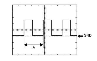
Using an oscilloscope, check waveform 1.
Waveform 1 (Reference) Item Condition Tester Connection
-
I10-19 (+S) - Body ground
-
I10-20 (SI) - Body ground
Tool Setting 5 V/DIV., 20 ms./DIV. Vehicle Condition Driving at approximately 20 km/h (12 mph) Tech Tips
When the system is functioning normally, one wheel revolution generates 4 pulses. As the vehicle speed increases, the width indicated by (A) in the illustration narrows.
-
-
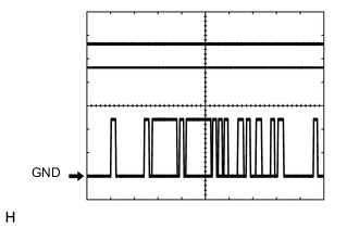
Using an oscilloscope, check waveform 2.
Waveform 2 (Reference) Item Condition Tester Connection I10-32 (TX-) - Body ground Tool Setting 5 V/DIV., 200 μs./DIV. Vehicle Condition Power switch on (IG) Tech Tips
The period of the signal changes depending on the communication state.
-
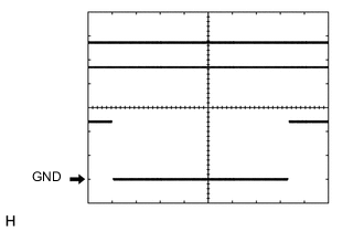
Using an oscilloscope, check waveform 3.
Waveform 3 (Reference) Item Condition Tester Connection I10-33 (CS) - Body ground Tool Setting 5 V/DIV., 2 ms./DIV. Vehicle Condition Power switch on (IG) Tech Tips
The period of the signal changes depending on the communication state.
-
-
-
COMBINATION METER MIRROR CONTROL ECU (w/ Headup Display)

-
Measure the voltage, resistance and waveform according to the value(s) in the table below.
Terminal No. (Symbol) Wiring Color Terminal Description Condition Specified Condition J5-1 (IG) - Body ground B - Body ground Power switch signal Power switch off Below 1 V Power switch on (IG) 11 to 14 V J5-2 (B) - Body ground G - Body ground Battery Power switch off 11 to 14 V J5-4 (ES) - Body ground W-B - Body ground Ground Always Below 1 Ω J5-5 (ACC) - Body ground GR - Body ground Power switch signal Power switch off Below 1 V Power switch on (ACC) 11 to 14 V J5-6 (TX-) - Body ground W - Body ground Headup display communication signal Power switch on (IG) Pulse generation (See waveform 1) J5-7 (CS) - Body ground Y - Body ground Headup display communication signal Power switch on (IG) Pulse generation (See waveform 2) J5-9 (SW1) - Body ground R - Body ground Headup display switch signal Power switch on (IG), headup display switch (HUD) off 4.7 to 5.5 V Power switch on (IG), headup display switch (HUD) on 0 to 0.6 V Power switch on (IG), headup display switch (DISP) off 4.7 to 5.5 V Power switch on (IG), headup display switch (DISP) on 0.8 to 1.6 V J5-10 (SW2) - Body ground L - Body ground Headup display switch signal Power switch on (IG), headup display switch (contrast up) off 4.7 to 5.5 V Power switch on (IG), headup display switch (contrast up) on 0.8 to 1.6 V Power switch on (IG), headup display switch (contrast down) off 4.7 to 5.5 V Power switch on (IG), headup display switch (contrast down) on 0 to 0.6 V Power switch on (IG), headup display switch (position up) off 4.7 to 5.5 V Power switch on (IG), headup display switch (position up) on 3.1 to 4.1 V Power switch on (IG), headup display switch (position down) off 4.7 to 5.5 V Power switch on (IG), headup display switch (position down) on 1.8 to 2.7 V J5-12 (MPX1) - Body ground L - Body ground Radio receiver assembly communication signal Power switch on (IG) Pulse generation J5-13 (MPX2) - Body ground LG - Body ground Radio receiver assembly communication signal Power switch on (IG) Pulse generation J5-16 (E) - Body ground B - Body ground Ground (Illumination ground) Always Below 1 Ω
-
Using an oscilloscope, check waveform 1.
Waveform 1 (Reference) Item Condition Tester Connection J5-6 (TX-) - Body ground Tool Setting 5 V/DIV., 200 μs./DIV. Vehicle Condition Power switch on (IG) Tech Tips
The period of the signal changes depending on the communication state.
-
Using an oscilloscope, check waveform 2.
Waveform 2 (Reference) Item Condition Tester Connection J5-7 (CS) - Body ground Tool Setting 5 V/DIV., 2 ms./DIV. Vehicle Condition Power switch on (IG) Tech Tips
The period of the signal changes depending on the communication state.
-
-