LIGHTING SYSTEM Interior Light Auto Cut Circuit
DESCRIPTION
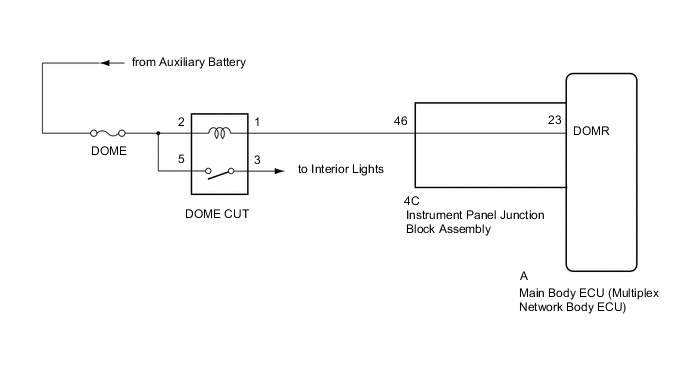
The main body ECU (multiplex network body ECU) controls the DOME CUT relay.
WIRING DIAGRAM
CAUTION / NOTICE / HINT
Note
-
Inspect the fuses for circuits related to this system before performing the following procedure.
-
If the main body ECU (multiplex network body ECU) is replaced, refer to the Service Bulletin.
PROCEDURE
-
READ VALUE USING GTS (RELAY FOR INTERIOR LIGHT AUTO CUT FUNCTION)
-
Using the GTS, read the Data List.
Body Electrical > Main Body > Active TestTester Display Measurement Item Control Range Diagnostic Note Relay for Interior Light Auto Cut Function DOME CUT relay ON or OFF Check the operation with the interior illumination on.
Body Electrical > Main Body > Active TestTester Display Relay for Interior Light Auto Cut Function OK Battery saving control (interior light auto cut function) operates. Result Proceed to OK NG
OK 
PROCEED TO NEXT SUSPECTED AREA SHOWN IN PROBLEM SYMPTOMS TABLE Click here
NG 
-
-
INSPECT DOME CUT RELAY
-
Remove the DOME CUT relay from the No. 3 relay block.
-
Inspect the DOME CUT relay.
Result Proceed to OK NG
NG
REPLACE DOME CUT RELAY
OK
-
-
CHECK HARNESS AND CONNECTOR (DOME CUT RELAY - BATTERY AND BODY GROUND)
-
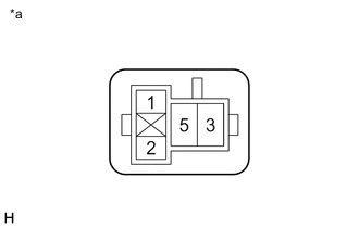
*a Front view of wire harness connector
(to DOME CUT Relay)
Measure the voltage according to the value(s) in the table below.
Standard Voltage Tester Connection Switch Condition Specified Condition 2 - Body ground Power switch off 11 to 14 V Result Proceed to OK NG
NG
REPAIR OR REPLACE HARNESS OR CONNECTOR
OK
-
-
CHECK HARNESS AND CONNECTOR (DOME CUT RELAY - INSTRUMENT PANEL JUNCTION BLOCK ASSEMBLY)
-
Disconnect the 4C instrument panel junction block assembly connectors.
-
Measure the resistance according to the value(s) in the table below.
Standard Resistance Tester Connection Condition Specified Condition DOME CUT relay terminal 1 - 4C-46 Always Below 1 Ω DOME CUT relay terminal 1 or 4C-46 - Body ground Always 10 kΩ or higher Result Proceed to OK NG
NG
REPAIR OR REPLACE HARNESS OR CONNECTOR
OK
-
-
INSPECT INSTRUMENT PANEL JUNCTION BLOCK ASSEMBLY
-
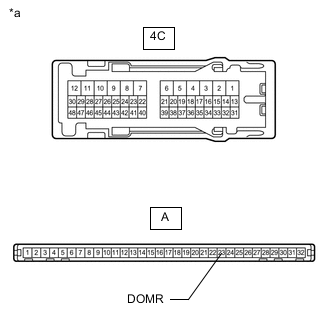
*a Component without harness connected
(Instrument Panel Junction Block Assembly)
Remove the instrument panel junction block assembly.
for LHD:
for RHD:
-
Remove the main body ECU (multiplex network body ECU) from the instrument panel junction block assembly.
for LHD:
for RHD:
-
Measure the resistance according to the value(s) in the table below.
Standard Resistance Tester Connection Condition Specified Condition 4C-46 - A-23 (DOMR) Always Below 1 Ω Result Proceed to OK NG
OK
REPLACE MAIN BODY ECU (MULTIPLEX NETWORK BODY ECU) for LHD: REPLACE MAIN BODY ECU (MULTIPLEX NETWORK BODY ECU) Click here
REPLACE MAIN BODY ECU (MULTIPLEX NETWORK BODY ECU) for RHD: REPLACE MAIN BODY ECU (MULTIPLEX NETWORK BODY ECU) Click hereNG
REPLACE INSTRUMENT PANEL JUNCTION BLOCK ASSEMBLY for LHD: REPLACE INSTRUMENT PANEL JUNCTION BLOCK ASSEMBLY Click here
REPLACE INSTRUMENT PANEL JUNCTION BLOCK ASSEMBLY for RHD: REPLACE INSTRUMENT PANEL JUNCTION BLOCK ASSEMBLY Click here -