TILT SENSOR REMOVAL
PROCEDURE
-
PRECAUTION
Note
After turning the power switch off, waiting time may be required before disconnecting the cable from the negative (-) auxiliary battery terminal. Therefore, make sure to read the disconnecting the cable from the negative (-) auxiliary battery terminal notice before proceeding with work.
-
DISCONNECT CABLE FROM NEGATIVE AUXILIARY BATTERY TERMINAL
CAUTION:
Wait at least 90 seconds after disconnecting the cable from the negative (-) auxiliary battery terminal to disable the SRS system.
Note
When disconnecting the cable, some systems need to be initialized after the cable is reconnected.
-
REMOVE DOOR SCUFF PLATE ASSEMBLY RH (for RHD)
-
REMOVE COWL SIDE TRIM BOARD RH (for RHD)
-
REMOVE CONSOLE ARMREST ASSEMBLY
-
REMOVE UPPER REAR CONSOLE PANEL
-
REMOVE UPPER NO. 1 CONSOLE PANEL GARNISH
-
REMOVE UPPER NO. 2 CONSOLE PANEL GARNISH
-
REMOVE INSTRUMENT SIDE PANEL RH
-
REMOVE INSTRUMENT SIDE PANEL LH
-
REMOVE NO. 1 INSTRUMENT PANEL SAFETY PAD SUB-ASSEMBLY
-
REMOVE NO. 1 INSTRUMENT PANEL UNDER COVER SUB-ASSEMBLY
-
REMOVE LOWER NO. 1 INSTRUMENT PANEL FINISH PANEL
-
REMOVE NO. 1 SWITCH HOLE BASE
-
REMOVE NO. 2 INSTRUMENT PANEL SAFETY PAD SUB-ASSEMBLY
-
REMOVE CENTER INSTRUMENT CLUSTER FINISH PANEL ASSEMBLY
-
REMOVE SHIFT LEVER KNOB SUB-ASSEMBLY
-
REMOVE UPPER REAR CONSOLE PANEL SUB-ASSEMBLY
-
REMOVE THEFT WARNING TILT SENSOR
-
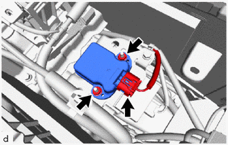
Disconnect the connector.
-
Remove the 2 nuts and theft warning tilt sensor.
Note
Do not remove the theft warning tilt sensor from the bracket.
-