DOOR CONTROL RELAY REMOVAL
PROCEDURE
-
PRECAUTION
Note
After turning the power switch off, waiting time may be required before disconnecting the cable from the negative (-) auxiliary battery terminal. Therefore, make sure to read the disconnecting the cable from the negative (-) auxiliary battery terminal notices before proceeding with work.
-
REMOVE DECK BOARD ASSEMBLY
-
REMOVE NO. 3 DECK BOARD SUB-ASSEMBLY (w/ Spare Tire)
-
REMOVE REAR DECK FLOOR BOX (w/ Spare Tire)
-
REMOVE DECK FLOOR BOX LH (w/ Spare Tire)
-
DISCONNECT CABLE FROM NEGATIVE AUXILIARY BATTERY TERMINAL
-
REMOVE NO. 2 INSTRUMENT PANEL UNDER COVER SUB-ASSEMBLY (for LHD)
-
REMOVE GLOVE COMPARTMENT DOOR ASSEMBLY (for LHD)
-
REMOVE DOOR SCUFF PLATE ASSEMBLY RH (for RHD)
-
REMOVE COWL SIDE TRIM BOARD RH (for RHD)
-
REMOVE CONSOLE ARMREST ASSEMBLY (for RHD)
-
REMOVE UPPER REAR CONSOLE PANEL (for RHD)
-
REMOVE UPPER NO. 1 CONSOLE PANEL GARNISH (for RHD)
-
REMOVE INSTRUMENT SIDE PANEL RH (for RHD)
-
REMOVE NO. 1 INSTRUMENT PANEL SAFETY PAD SUB-ASSEMBLY (for RHD)
-
REMOVE NO. 1 INSTRUMENT PANEL UNDER COVER SUB-ASSEMBLY (for RHD)
-
REMOVE LOWER NO. 1 INSTRUMENT PANEL FINISH PANEL (for RHD)
-
REMOVE ECU INTEGRATION BOX RH (for LHD)
-
REMOVE ECU INTEGRATION BOX RH (for RHD)
-
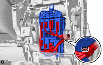
Disconnect the connectors.
-
Detach the clamp.
-

Nut 
Bolt Remove the 2 nuts and bolt.
-
Detach the clamp and remove the ECU integration box RH.
-
-
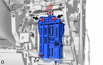
REMOVE DOUBLE LOCK DOOR CONTROL RELAY ASSEMBLY (for LHD)
-
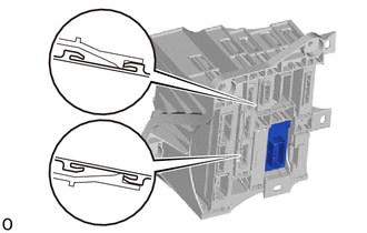
Detach the 2 claws and remove the double lock door control relay assembly.
-
-
REMOVE DOUBLE LOCK DOOR CONTROL RELAY ASSEMBLY (for RHD)
-
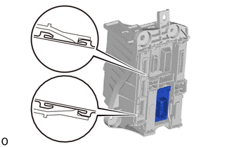
Detach the 2 claws and remove the double lock door control relay assembly.
-