REAR DOOR LOCK INSTALLATION
CAUTION / NOTICE / HINT
Tech Tips
-
Use the same procedure for the RH and LH sides.
-
The procedure listed below is for the LH side.
-
A bolt without a torque specification is shown in the standard bolt chart.
PROCEDURE
-
INSTALL REAR DOOR INSIDE LOCKING CABLE ASSEMBLY LH
-
w/o Double Locking System:
-
Attach the clamp to install the rear door inside locking cable assembly LH to the rear door lock assembly LH.
-
-
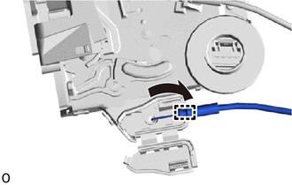
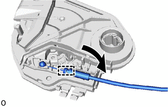
w/ Double Locking System:
-
Attach the clamp to install the rear door inside locking cable assembly LH to the rear door lock assembly LH.
-
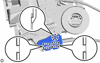
Attach the 2 clamps.
-
Attach the claw to close the cover.
-
-
-
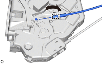
INSTALL REAR DOOR LOCK REMOTE CONTROL CABLE ASSEMBLY LH
-
w/o Double Locking System:
-
Attach the clamp to install the rear door lock remote control cable assembly LH to the rear door lock assembly LH.
-
-
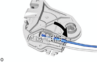
w/ Double Locking System:
-
Attach the clamp to install the rear door lock remote control cable assembly LH to the rear door lock assembly LH.
-
-
-
INSTALL REAR DOOR LOCK COVER SUB-ASSEMBLY LH
-
Attach the 2 guides.
-
Attach the 2 claws to install the rear door lock cover sub-assembly LH.
-
-
INSTALL REAR DOOR LOCK ASSEMBLY LH
Note
-
When reusing the removed rear door lock assembly, replace the door lock wiring harness seal on the connector with a new one.
-
Do not allow grease or dust to contact the door lock wiring harness seal surface of the connector.
-
Reusing the door lock wiring harness seal or using a damaged door lock wiring harness seal may cause water intrusion. This may result in a malfunction of the rear door lock assembly.
-
Apply MP grease to the sliding parts of the rear door lock assembly LH.
-
Install a new door lock wiring harness seal to the rear door lock assembly LH.
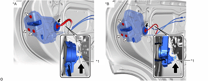
*A w/o Double Locking System *B w/ Double Locking System *1 Release Plate - - 
Upward - - -
Insert the rear door lock assembly LH into the rear door outside handle frame release plate, and set it to the rear door panel.
-
Make sure that the rear door outside handle frame release plate is securely connected to the rear door lock assembly LH.
-
Using a T30 "TORX" socket wrench, install the rear door lock assembly LH with the 3 screws.
- Torque:
- 5.0 N*m { 51 kgf*cm, 44 in.*lbf }
-
Connect the connector.
-
-
INSTALL REAR DOOR GLASS SUB-ASSEMBLY LH
-
INSTALL REAR DOOR REAR GUIDE SEAL LH
-
INSTALL REAR DOOR REAR LOWER WINDOW FRAME SUB-ASSEMBLY LH
-
INSTALL REAR DOOR GLASS RUN LH
-
INSTALL REAR DOOR SERVICE HOLE COVER LH
-
INSTALL REAR DOOR ARMREST SET BRACKET LH
-
INSTALL REAR DOOR INNER GLASS WEATHERSTRIP LH
-
INSTALL REAR DOOR TRIM BOARD SUB-ASSEMBLY LH
-
INSTALL REAR POWER WINDOW REGULATOR SWITCH ASSEMBLY WITH REAR DOOR ARMREST BASE PANEL
-
INSTALL REAR DOOR INSIDE HANDLE BEZEL PLUG LH
-
INSTALL REAR DOOR TRIM COVER LH
-
INSTALL DECK FLOOR BOX LH (w/ Spare Tire)
-
INSTALL REAR DECK FLOOR BOX (w/ Spare Tire)
-
INSTALL NO. 3 DECK BOARD SUB-ASSEMBLY (w/ Spare Tire)
-
INSTALL DECK BOARD ASSEMBLY
-
CONNECT CABLE TO NEGATIVE BATTERY TERMINAL
Note
When disconnecting the cable, some systems need to be initialized after the cable is reconnected.
-
INITIALIZE CABLE TO NEGATIVE AUXILIARY BATTERY TERMINAL
-
CHECK POWER WINDOW CONTROL SYSTEM
-
CHECK POWER DOOR LOCK CONTROL SYSTEM