CAN COMMUNICATION SYSTEM(for RHD), Diagnostic DTC:U0100, U0129, U0293
| DTC Code | DTC Name |
|---|---|
| U0100 | Lost Communication with ECM / PCM "A" |
| U0129 | Lost Communication with Brake System Control Module |
| U0293 | Lost Communication with Hybrid Vehicle Control System |
DESCRIPTION
-
The hybrid vehicle control ECU communicates with the ECM and brake booster with master cylinder assembly (skid control ECU). When the hybrid vehicle control ECU does not receive data from the ECM or brake booster with master cylinder assembly (skid control ECU), the hybrid vehicle control ECU stores DTC U0100 or U0129.
-
The ECM communicates with the hybrid vehicle control ECU. When the ECM does not receive data from the hybrid vehicle control ECU, the ECM stores DTC U0293.
-
The brake booster with master cylinder assembly (skid control ECU) communicates with the hybrid vehicle control ECU. When the brake booster with master cylinder assembly (skid control ECU) does not receive data from the hybrid vehicle control ECU, the brake booster with master cylinder assembly (skid control ECU) stores DTC U0293.
| DTC No. | Detection Item | DTC Detection Condition | Trouble Area | DTC Output from |
|---|---|---|---|---|
| U0100 | Lost Communication with ECM / PCM "A" | The hybrid vehicle control ECU does not receive data from the ECM. |
|
Hybrid vehicle control ECU |
| U0129 | Lost Communication with Brake System Control Module | The hybrid vehicle control ECU does not receive data from the brake booster with master cylinder assembly (skid control ECU). |
|
Hybrid vehicle control ECU |
| U0293 | Lost Communication with Hybrid Vehicle Control System |
|
|
|
WIRING DIAGRAM
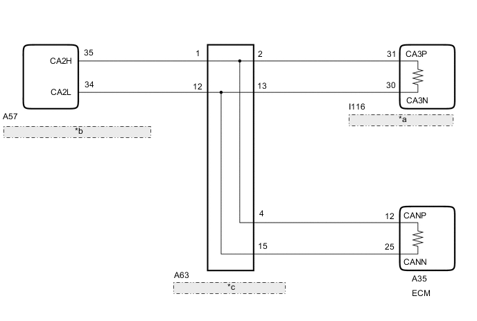
| *a | Hybrid Vehicle Control ECU |
| *b | Brake Booster with Master Cylinder Assembly (Skid Control ECU) |
| *c | No. 1 CAN Junction Connector |
CAUTION / NOTICE / HINT
Note
-
Before measuring the resistance of the CAN bus, turn the power switch off and leave the vehicle for 1 minute or more without operating the key, switches or opening or closing the doors. After that, disconnect the cable from the negative (-) auxiliary battery terminal and leave the vehicle for 1 minute or more before measuring the resistance.
-
After turning the power switch off, waiting time may be required before disconnecting the cable from the negative (-) auxiliary battery terminal. Therefore, make sure to read the disconnecting the cable from the negative (-) auxiliary battery terminal notices before proceeding with work.
-
Because the order of diagnosis is important to allow correct diagnosis, make sure to begin troubleshooting using How to Proceed with Troubleshooting when CAN communication system related DTCs are output.
-
DTC check procedure: Drive the vehicle at a speed of 15 km/h (9 mph) or more for 3 seconds or more.
-
After the repair, perform the CAN bus check and check that all the ECUs and sensors connected to the CAN communication system are displayed.
Tech Tips
-
Operating the power switch, any other switches or a door triggers related ECU and sensor communication on the CAN. This communication will cause the resistance value to change.
-
Even after DTCs are cleared, if a DTC is stored again after driving the vehicle for a while, the malfunction may be occurring due to vibration of the vehicle. In such a case, wiggling the ECUs or wire harness while performing the inspection below may help determine the cause of the malfunction.
PROCEDURE
-
CHECK FOR DTC
-
Check for DTCs.
Powertrain > Hybrid Control > Trouble CodesTech Tips
If the hybrid vehicle control ECU outputs only DTC U0129, troubleshoot DTC U0129 and check the branch circuit of sub bus 15.
Result Result Proceed to The hybrid vehicle control ECU outputs DTC U0129 and other DTCs. A The hybrid vehicle control ECU outputs only DTC U0129. B
B 
GO TO DIAGNOSIS PROCEDURE INDICATED BY OUTPUT DTC Click here
A 
-
-
CHECK SUB BUS 15
-
Disconnect the cable from the negative (-) auxiliary battery terminal.
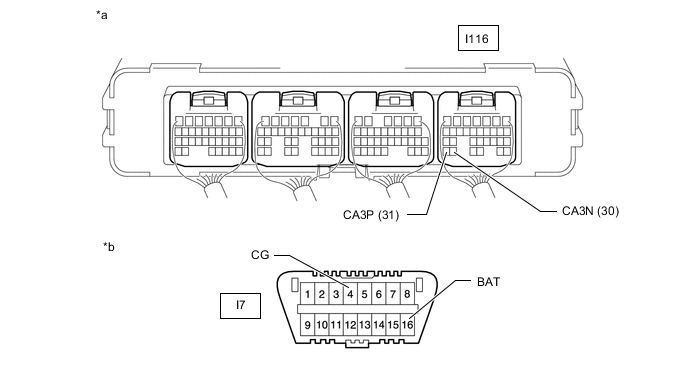
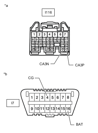
*a Component with harness connected
(Hybrid Vehicle Control ECU)
*b Front view of DLC3 -
Measure the resistance according to the value(s) in the table below.
Standard Resistance Tester Connection Condition Specified Condition Result I116-31 (CA3P) - I116-30 (CA3N) Cable disconnected from negative (-) auxiliary battery terminal 54 to 69 Ω Below 53 Ω: Short in line I116-31 (CA3P) - I116-30 (CA3N) Cable disconnected from negative (-) auxiliary battery terminal 54 to 69 Ω 70 Ω or higher: Open in CAN main bus line I116-31 (CA3P) - I7-4 (CG) Cable disconnected from negative (-) auxiliary battery terminal 200 Ω or higher Below 200 Ω: Ground short I116-30 (CA3N) - I7-4 (CG) Cable disconnected from negative (-) auxiliary battery terminal 200 Ω or higher Below 200 Ω: Ground short I116-31 (CA3P) - I7-16 (BAT) Cable disconnected from negative (-) auxiliary battery terminal 6 kΩ or higher Below 6 kΩ: +B short I116-30 (CA3N) - I7-16 (BAT) Cable disconnected from negative (-) auxiliary battery terminal 6 kΩ or higher Below 6 kΩ: +B short Result Result Proceed to OK A NG
- Open in CAN main wire
B NG
- Short in CAN bus wire
C NG
- +B short
- Ground short
D
A
REPLACE HYBRID VEHICLE CONTROL ECU Click here
C 
CHECK FOR SHORT IN CAN BUS WIRES (HYBRID VEHICLE CONTROL ECU) Click here
D
CHECK FOR SHORT IN CAN BUS WIRES (NO. 1 CAN JUNCTION CONNECTOR) Click here
B
-
-
CHECK FOR OPEN IN CAN BUS MAIN WIRE (HYBRID VEHICLE CONTROL ECU)
-

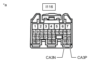
*a Front view of wire harness connector
(to Hybrid Vehicle Control ECU)
Disconnect the hybrid vehicle control ECU connector.
-
Measure the resistance according to the value(s) in the table below.
Standard Resistance Tester Connection Condition Specified Condition I116-31 (CA3P) - I116-30 (CA3N) Cable disconnected from negative (-) auxiliary battery terminal 108 to 132 Ω Result Proceed to OK NG
OK
REPLACE HYBRID VEHICLE CONTROL ECU Click here
NG
-
-
CONNECT CONNECTOR
-
Reconnect the I116 hybrid vehicle control ECU connector.
Result Proceed to NEXT
NEXT
-
-
CHECK FOR OPEN IN CAN BUS MAIN WIRE (NO. 1 CAN JUNCTION CONNECTOR)
-
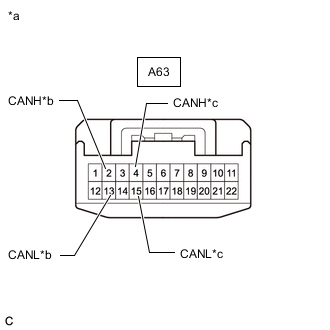
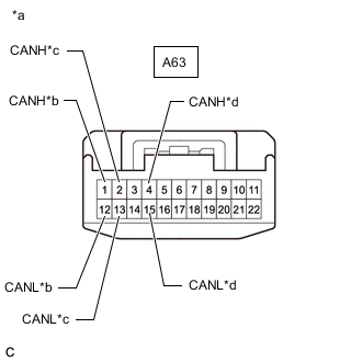
*a Front view of wire harness connector
(to No. 1 CAN Junction Connector)
*b to Hybrid Vehicle Control ECU *c to ECM Disconnect the No. 1 CAN junction connector.
-
Measure the resistance according to the value(s) in the table below.
Standard Resistance Tester Connection Condition Specified Condition Connected to A63-2 (CANH) - A63-13 (CANL) Cable disconnected from negative (-) auxiliary battery terminal 108 to 132 Ω Hybrid Vehicle Control ECU A63-4 (CANH) - A63-15 (CANL) Cable disconnected from negative (-) auxiliary battery terminal 108 to 132 Ω ECM Result Result Proceed to OK A NG (to hybrid vehicle control ECU CAN main wire) B NG (to ECM CAN main wire) C
A
REPLACE NO. 1 CAN JUNCTION CONNECTOR
B
REPAIR OR REPLACE CAN MAIN WIRE OR CONNECTOR (NO. 1 CAN JUNCTION CONNECTOR - HYBRID VEHICLE CONTROL ECU)
C
-
-
CONNECT CONNECTOR
-
Reconnect the A63 No. 1 CAN junction connector.
Result Proceed to NEXT
NEXT
-
-
CHECK FOR OPEN IN CAN BUS MAIN WIRE (ECM)
-

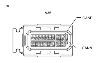
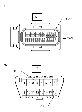
*a Front view of wire harness connector
(to ECM)
Disconnect the ECM connector.
-
Measure the resistance according to the value(s) in the table below.
Standard Resistance Tester Connection Condition Specified Condition A35-12 (CANP) - A35-25 (CANN) Cable disconnected from negative (-) auxiliary battery terminal 108 to 132 Ω Result Proceed to OK NG
OK
REPLACE ECM Click here
NG
REPAIR OR REPLACE CAN MAIN WIRE OR CONNECTOR (NO. 1 CAN JUNCTION CONNECTOR - ECM)
-
-
CHECK FOR SHORT IN CAN BUS WIRES (HYBRID VEHICLE CONTROL ECU)
-
*a Front view of wire harness connector
(to Hybrid Vehicle Control ECU)
Disconnect the hybrid vehicle control ECU connector.
-
Measure the resistance according to the value(s) in the table below.
Standard Resistance Tester Connection Condition Specified Condition I116-31 (CA3P) - I116-30 (CA3N) Cable disconnected from negative (-) auxiliary battery terminal 108 to 132 Ω Result Proceed to OK NG
OK
REPLACE HYBRID VEHICLE CONTROL ECU Click here
NG
-
-
CONNECT CONNECTOR
-
Reconnect the I116 hybrid vehicle control ECU connector.
Result Proceed to NEXT
NEXT
-
-
CHECK FOR SHORT IN CAN BUS WIRES (NO. 1 CAN JUNCTION CONNECTOR)
-
*a Front view of wire harness connector
(to No. 1 CAN Junction Connector)
*b to Brake Booster with Master Cylinder Assembly (Skid Control ECU) *c to Hybrid Vehicle Control ECU *d to ECM Disconnect the No. 1 CAN junction connector.
-
Measure the resistance according to the value(s) in the table below.
Standard Resistance Tester Connection Condition Specified Condition Connected to A63-1 (CANH) - A63-12 (CANL) Cable disconnected from negative (-) auxiliary battery terminal 108 to 132 Ω Brake Booster with Master Cylinder Assembly (Skid Control ECU) A63-2 (CANH) - A63-13 (CANL) Cable disconnected from negative (-) auxiliary battery terminal 200 Ω or higher Hybrid Vehicle Control ECU A63-4 (CANH) - A63-15 (CANL) Cable disconnected from negative (-) auxiliary battery terminal 108 to 132 Ω ECM Result Result Proceed to OK A NG (to hybrid vehicle control ECU CAN main wire) B NG (to ECM CAN main wire) C NG (to brake booster with master cylinder assembly [skid control ECU] CAN branch wire) D
A
REPLACE NO. 1 CAN JUNCTION CONNECTOR
B
REPAIR OR REPLACE CAN MAIN WIRE OR CONNECTOR (NO. 1 CAN JUNCTION CONNECTOR - HYBRID VEHICLE CONTROL ECU)
D
CONNECT CONNECTOR Click here
C
-
-
CONNECT CONNECTOR
-
Reconnect the A63 No. 1 CAN junction connector.
Result Proceed to NEXT
NEXT
-
-
CHECK FOR SHORT IN CAN BUS WIRES (ECM)
-
*a Front view of wire harness connector
(to ECM)
Disconnect the ECM connector.
-
Measure the resistance according to the value(s) in the table below.
Standard Resistance Tester Connection Condition Specified Condition A35-12 (CANP) - A35-25 (CANN) Cable disconnected from negative (-) auxiliary battery terminal 108 to 132 Ω Result Proceed to OK NG
OK
REPLACE ECM Click here
NG
REPAIR OR REPLACE CAN MAIN WIRE OR CONNECTOR (NO. 1 CAN JUNCTION CONNECTOR - ECM)
-
-
CONNECT CONNECTOR
-
Reconnect the A63 No. 1 CAN junction connector.
Result Proceed to NEXT
NEXT
-
-
CHECK FOR SHORT IN CAN BUS WIRES (SKID CONTROL ECU)
-
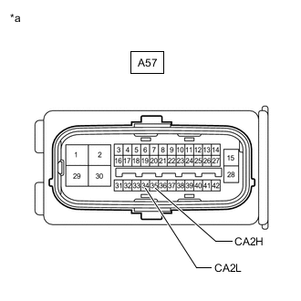
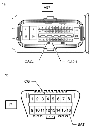
*a Front view of wire harness connector
(to Brake Booster with Master Cylinder Assembly [Skid Control ECU])
Disconnect the brake booster with master cylinder assembly (skid control ECU) connector.
-
Measure the resistance according to the value(s) in the table below.
Standard Resistance Tester Connection Condition Specified Condition A57-35 (CA2H) - A57-34 (CA2L) Cable disconnected from negative (-) auxiliary battery terminal 54 to 69 Ω Result Proceed to OK NG
OK
REPLACE BRAKE BOOSTER WITH MASTER CYLINDER ASSEMBLY Click here
NG
REPAIR OR REPLACE CAN BRANCH WIRE OR CONNECTOR (NO. 1 CAN JUNCTION CONNECTOR - SKID CONTROL ECU)
-
-
CHECK FOR SHORT IN CAN BUS WIRES (NO. 1 CAN JUNCTION CONNECTOR)
-
Disconnect the No. 1 CAN junction connector.
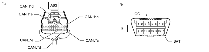
*a Rear view of wire harness connector
(to No. 1 CAN Junction Connector)
*b Front view of DLC3 *c to Brake Booster with Master Cylinder Assembly (Skid Control ECU) *d to Hybrid Vehicle Control ECU *e to ECM - - -
Measure the resistance according to the value(s) in the table below.
Standard Resistance Tester Connection Condition Specified Condition Purpose Connected to A63-1 (CANH) - I7-4 (CG) Cable disconnected from negative (-) auxiliary battery terminal 200 Ω or higher Inspection for CANH ground short Brake Booster with Master Cylinder Assembly (Skid Control ECU) A63-12 (CANL) - I7-4 (CG) Cable disconnected from negative (-) auxiliary battery terminal 200 Ω or higher Inspection for CANL ground short A63-1 (CANH) - I7-16 (BAT) Cable disconnected from negative (-) auxiliary battery terminal 6 kΩ or higher Inspection for CANH +B short A63-12 (CANL) - I7-16 (BAT) Cable disconnected from negative (-) auxiliary battery terminal 6 kΩ or higher Inspection for CANL +B short A63-2 (CANH) - I7-4 (CG) Cable disconnected from negative (-) auxiliary battery terminal 200 Ω or higher Inspection for CANH ground short Hybrid Vehicle Control ECU A63-13 (CANL) - I7-4 (CG) Cable disconnected from negative (-) auxiliary battery terminal 200 Ω or higher Inspection for CANL ground short A63-2 (CANH) - I7-16 (BAT) Cable disconnected from negative (-) auxiliary battery terminal 6 kΩ or higher Inspection for CANH +B short A63-13 (CANL) - I7-16 (BAT) Cable disconnected from negative (-) auxiliary battery terminal 6 kΩ or higher Inspection for CANL +B short A63-4 (CANH) - I7-4 (CG) Cable disconnected from negative (-) auxiliary battery terminal 200 Ω or higher Inspection for CANH ground short ECM A63-15 (CANL) - I7-4 (CG) Cable disconnected from negative (-) auxiliary battery terminal 200 Ω or higher Inspection for CANL ground short A63-4 (CANH) - I7-16 (BAT) Cable disconnected from negative (-) auxiliary battery terminal 6 kΩ or higher Inspection for CANH +B short A63-15 (CANL) - I7-16 (BAT) Cable disconnected from negative (-) auxiliary battery terminal 6 kΩ or higher Inspection for CANL +B short Result Result Proceed to OK A NG (to hybrid vehicle control ECU CAN main wire) B NG (to ECM CAN main wire) C NG (to brake booster with master cylinder assembly [skid control ECU] CAN branch wire) D
A
REPLACE NO. 1 CAN JUNCTION CONNECTOR
C
CONNECT CONNECTOR Click here
D
CONNECT CONNECTOR Click here
B
-
-
CONNECT CONNECTOR
-
Reconnect the A63 No. 1 CAN junction connector.
Result Proceed to NEXT
NEXT
-
-
CHECK FOR SHORT IN CAN BUS WIRES (HYBRID VEHICLE CONTROL ECU)
-
*a Front view of wire harness connector
(to Hybrid Vehicle Control ECU)
*b Front view of DLC3 Disconnect the hybrid vehicle control ECU connector.
-
Measure the resistance according to the value(s) in the table below.
Standard Resistance Tester Connection Condition Specified Condition I116-31 (CA3P) - I7-4 (CG) Cable disconnected from negative (-) auxiliary battery terminal 200 Ω or higher I116-30 (CA3N) - I7-4 (CG) Cable disconnected from negative (-) auxiliary battery terminal I116-31 (CA3P) - I7-16 (BAT) Cable disconnected from negative (-) auxiliary battery terminal 6 kΩ or higher I116-30 (CA3N) - I7-16 (BAT) Cable disconnected from negative (-) auxiliary battery terminal Result Proceed to OK NG
OK
REPLACE HYBRID VEHICLE CONTROL ECU Click here
NG
REPAIR OR REPLACE CAN MAIN WIRE OR CONNECTOR (HYBRID VEHICLE CONTROL ECU - NO. 1 CAN JUNCTION CONNECTOR)
-
-
CONNECT CONNECTOR
-
Reconnect the A63 No. 1 CAN junction connector.
Result Proceed to NEXT
NEXT
-
-
CHECK FOR SHORT IN CAN BUS WIRES (ECM)
-
*a Front view of wire harness connector
(to ECM)
*b Front view of DLC3 Disconnect the ECM connector.
-
Measure the resistance according to the value(s) in the table below.
Standard Resistance Tester Connection Condition Specified Condition A35-12 (CANP) - I7-4 (CG) Cable disconnected from negative (-) auxiliary battery terminal 200 Ω or higher A35-25 (CANN) - I7-4 (CG) Cable disconnected from negative (-) auxiliary battery terminal A35-12 (CANP) - I7-16 (BAT) Cable disconnected from negative (-) auxiliary battery terminal 6 kΩ or higher A35-25 (CANN) - I7-16 (BAT) Cable disconnected from negative (-) auxiliary battery terminal Result Proceed to OK NG
OK
REPLACE ECM Click here
NG
REPAIR OR REPLACE CAN MAIN WIRE OR CONNECTOR (ECM - NO. 1 CAN JUNCTION CONNECTOR)
-
-
CONNECT CONNECTOR
-
Reconnect the A63 No. 1 CAN junction connector.
Result Proceed to NEXT
NEXT
-
-
CHECK FOR SHORT IN CAN BUS WIRES (SKID CONTROL ECU)
-
*a Front view of wire harness connector
(to Brake Booster with Master Cylinder Assembly [Skid Control ECU])
*b Front view of DLC3 Disconnect the brake booster with master cylinder assembly (skid control ECU) connector.
-
Measure the resistance according to the value(s) in the table below.
Standard Resistance Tester Connection Condition Specified Condition A57-35 (CA2H) - I7-4 (CG) Cable disconnected from negative (-) auxiliary battery terminal 200 Ω or higher A57-34 (CA2L) - I7-4 (CG) Cable disconnected from negative (-) auxiliary battery terminal A57-35 (CA2H) - I7-16 (BAT) Cable disconnected from negative (-) auxiliary battery terminal 6 kΩ or higher A57-34 (CA2L) - I7-16 (BAT) Cable disconnected from negative (-) auxiliary battery terminal Result Proceed to OK NG
OK
REPLACE BRAKE BOOSTER WITH MASTER CYLINDER ASSEMBLY Click here
NG
REPAIR OR REPLACE CAN BRANCH WIRE OR CONNECTOR (SKID CONTROL ECU - NO. 1 CAN JUNCTION CONNECTOR)
-