CAN COMMUNICATION SYSTEM(for RHD) TERMINALS OF ECU
Tech Tips
Operating the power switch, any switches or any doors triggers related ECU and sensor communication with the CAN, which causes resistance variation.
-
DISCONNECT CABLE FROM NEGATIVE AUXILIARY BATTERY TERMINAL
-
Disconnect the cable from the negative (-) auxiliary battery terminal before measuring the resistances of the CAN main wire and CAN branch wire.
CAUTION:
Wait at least 90 seconds after disconnecting the cable from the negative (-) auxiliary battery terminal to disable the SRS system.
Note
-
Before measuring the resistance, leave the vehicle for at least 1 minute and do not operate the power switch, any switches or any doors. If doors need to be opened in order to check connectors, open the doors and leave them open.
-
After turning the power switch off, waiting time may be required before disconnecting the cable from the negative (-) auxiliary battery terminal. Therefore, make sure to read the disconnecting the cable from the auxiliary battery terminal notice before proceeding with work.
-
When disconnecting the cable, some systems need to be initialized after the cable is reconnected.
-
-
-
JUNCTION CONNECTOR
-
No. 1 CAN Junction Connector
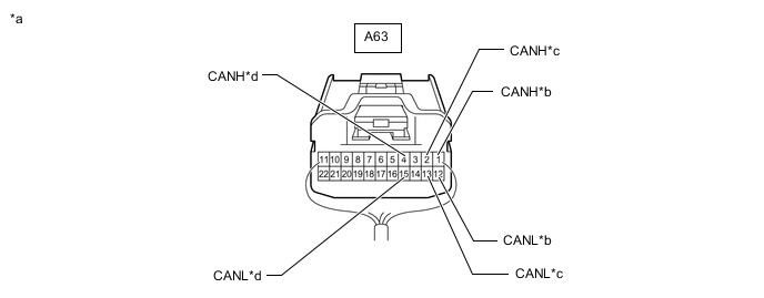
*a Rear view of wire harness connector
(to No. 1 CAN Junction Connector)
*b for Brake Booster with Master Cylinder Assembly (Skid Control ECU) *c for Hybrid Vehicle Control ECU *d for ECM No. 1 CAN Junction Connector Wiring Color Connect to A63-1 (CANH) B Brake booster with master cylinder assembly (skid control ECU) A63-12 (CANL) W A63-2 (CANH) V Hybrid vehicle control ECU A63-13 (CANL) W A63-4 (CANH) R ECM A63-15 (CANL) W -
No. 2 CAN Junction Connector
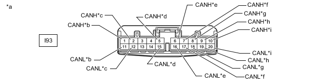
*a Front view of wire harness connector
(to No. 2 CAN Junction Connector)
*b for Air Conditioning Amplifier Assembly *c for Power Steering ECU Assembly *d for No. 3 CAN Junction Connector *e for Certification ECU (Smart Key ECU Assembly) *f for Combination Meter Assembly *g for DLC3 *h for Spiral with Sensor Cable Sub-assembly (Steering Angle Sensor) *i for Airbag ECU Assembly - - No. 2 CAN Junction Connector Wiring Color Connect to I93-1 (CANH) P Air conditioning amplifier assembly I93-11 (CANL) W I93-2 (CANH) LG Power steering ECU assembly I93-12 (CANL) W I93-5 (CANH) V No. 3 CAN junction connector I93-15 (CANL) W I93-6 (CANH) R Certification ECU (smart key ECU assembly) I93-16 (CANL) W I93-7 (CANH) G Combination meter assembly I93-17 (CANL) W I93-8 (CANH) B DLC3 I93-18 (CANL) W I93-9 (CANH) P Spiral with sensor cable sub-assembly (steering angle sensor) I93-19 (CANL) W I93-10 (CANH) B Airbag ECU assembly I93-20 (CANL) W -
No. 3 CAN Junction Connector
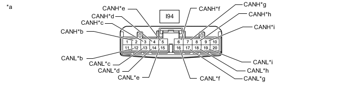
*a Front view of wire harness connector
(to No. 3 CAN Junction Connector)
*b for Stereo Component Equalizer Assembly (w/ ASC System) *c for Parking Brake ECU Assembly *d for Main Body ECU (Multiplex Network Body ECU) *e for Radio Receiver Assembly (w/ Navigation System or Audio and Visual System) *f for No. 2 CAN Junction Connector *g for ECM *h for Brake Booster with Master Cylinder Assembly (Skid Control ECU) *i for Hybrid Vehicle Control ECU - - No. 3 CAN Junction Connector Wiring Color Connect to I94-2 (CANH) R Stereo component equalizer assembly*1 I94-12 (CANL) W I94-3 (CANH) B Parking brake ECU assembly I94-13 (CANL) W I94-4 (CANH) Y Main body ECU (multiplex network body ECU) I94-14 (CANL) W I94-5 (CANH) Y Radio receiver assembly*2 I94-15 (CANL) W I94-6 (CANH) V No. 2 CAN junction connector I94-16 (CANL) W I94-7 (CANH) Y ECM I94-17 (CANL) W I94-8 (CANH) R Brake booster with master cylinder assembly (skid control ECU) I94-18 (CANL) W I94-9 (CANH) LG Hybrid vehicle control ECU I94-19 (CANL) W *1: w/ ASC System
*2: w/ Navigation System or Audio and Visual System
-
No. 4 CAN Junction Connector
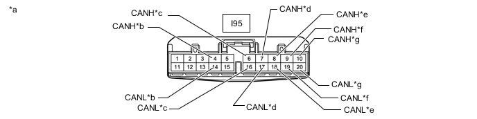
*a Front view of wire harness connector
(to No. 4 CAN Junction Connector)
*b for Hybrid Vehicle Control ECU *c for Clearance Warning ECU Assembly (w/ LEXUS Parking Assist-sensor System) *d for Driving Support ECU Assembly (w/ Pre-crash Safety System) *e for Lane Departure Warning Camera (w/ Lane Departure Alert System) *f for Parking Assist ECU (w/ Panoramic View Monitor System) *g for No. 8 CAN Junction Connector - - No. 4 CAN Junction Connector Wiring Color Connect to I95-4 (CANH) P Hybrid vehicle control ECU I95-14 (CANL) W I95-6 (CANH) R Clearance warning ECU assembly*1 I95-16 (CANL) W I95-7 (CANH) V Driving support ECU assembly*2 I95-17 (CANL) W I95-8 (CANH) B Lane departure warning camera*3 I95-18 (CANL) W I95-9 (CANH) G Parking assist ECU*4 I95-19 (CANL) W I95-10 (CANH) Y No. 8 CAN junction connector I95-20 (CANL) W *1: w/ LEXUS Parking Assist-sensor System
*2: w/ Pre-crash Safety System
*3: w/ Lane Departure Alert System
*4: w/ Panoramic View Monitor System
-
No. 5 CAN Junction Connector
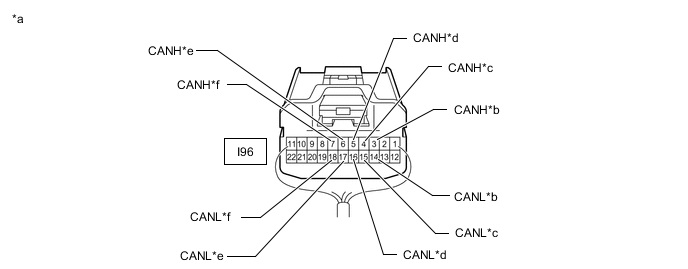
*a Rear view of wire harness connector
(to No. 5 CAN Junction Connector)
*b for Multiplex Tilt and Telescopic ECU (for Power Tilt and Power Telescopic Steering Column) *c for Main Body ECU (Multiplex Network Body ECU) *d for Outer Mirror Control ECU Assembly RH (w/ Memory) *e for Front Power Seat Switch RH (w/ Memory) *f for No. 6 CAN Junction Connector No. 5 CAN Junction Connector Wiring Color Connect to I96-3 (CANH) G Multiplex tilt and telescopic ECU*1 I96-14 (CANL) W I96-4 (CANH) B Main body ECU (multiplex network body ECU) I96-15 (CANL) W I96-5 (CANH) R Outer mirror control ECU assembly RH*2 I96-16 (CANL) W I96-6 (CANH) GR Front power seat switch RH*2 I96-17 (CANL) W I96-7 (CANH) V No. 6 CAN junction connector I96-18 (CANL) W *1: for Power Tilt and Power Telescopic Steering Column
*2: w/ Memory
-
No. 6 CAN Junction Connector
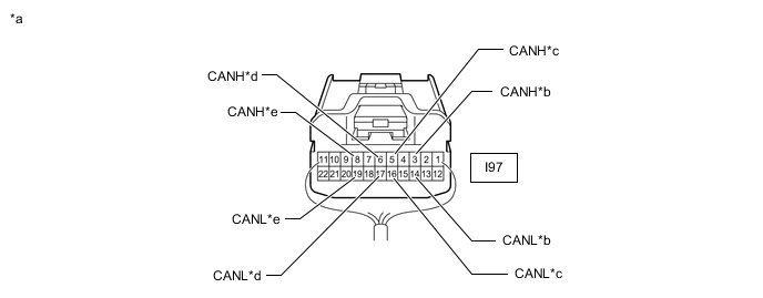
*a Rear view of wire harness connector
(to No. 6 CAN Junction Connector)
*b for Headlight Light Control ECU Sub-assembly LH *c for No. 9 CAN Junction Connector *d for No. 5 CAN Junction Connector *e for Outer Mirror Control ECU Assembly LH (w/ Memory) - - No. 6 CAN Junction Connector Wiring Color Connect to I97-3 (CANH) B Headlight light control ECU sub-assembly LH I97-14 (CANL) W I97-5 (CANH) L No. 9 CAN junction connector I97-16 (CANL) W I97-6 (CANH) V No. 5 CAN junction connector I97-17 (CANL) W I97-8 (CANH) B Outer mirror control ECU assembly LH* I97-19 (CANL) W *: w/ Memory
-
No. 8 CAN Junction Connector
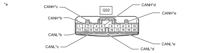
*a Front view of wire harness connector
(to No. 8 CAN Junction Connector)
*b for Blind Spot Monitor Sensor LH (w/ Blind Spot Monitor System) *c for No. 1 CAN Junction Terminal *d for No. 4 CAN Junction Connector *e for Absorber Control ECU (w/ Adaptive Variable Suspension System) - - No. 8 CAN Junction Connector Wiring Color Connect to Q32-3 (CANH) R Blind spot monitor sensor LH*1 Q32-13 (CANL) W Q32-4 (CANH) G No. 1 CAN junction terminal Q32-14 (CANL) W Q32-5 (CANH) L No. 4 CAN junction connector Q32-15 (CANL) W Q32-7 (CANH) B Absorber control ECU*2 Q32-17 (CANL) W *1: w/ Blind Spot Monitor System
*2: w/ Adaptive Variable Suspension System
-
No. 9 CAN Junction Connector
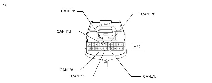
*a Rear view of wire harness connector
(to No. 9 CAN Junction Connector)
*b for No. 6 CAN Junction Connector *c for Multiplex Network Door ECU (w/ Power Back Door System) *d for No. 2 CAN Junction Terminal No. 9 CAN Junction Connector Wiring Color Connect to Y22-5 (CANH) G No. 6 CAN junction connector Y22-16 (CANL) W Y22-6 (CANH) G Multiplex network door ECU* Y22-17 (CANL) W Y22-7 (CANH) G No. 2 CAN junction terminal Y22-18 (CANL) W *: w/ Power Back Door System
-
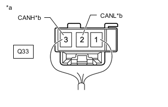
*a Rear view of wire harness connector
(to No. 1 CAN Junction Terminal)
*b for No. 8 CAN Junction Connector No. 1 CAN Junction Terminal
No. 1 CAN Junction Terminal Wiring Color Connect to Q33-2 (CANL) W No. 8 CAN junction connector Q33-3 (CANH) G -
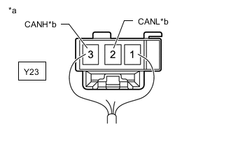
*a Rear view of wire harness connector
(to No. 2 CAN Junction Terminal)
*b for No. 9 CAN Junction Connector No. 2 CAN Junction Terminal
No. 2 CAN Junction Terminal Wiring Color Connect to Y23-2 (CANL) W No. 9 CAN junction connector Y23-3 (CANH) G
-
-
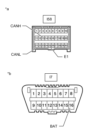
CHECK DLC3
-

*a Front view of DLC3 Disconnect the cable from the negative (-) auxiliary battery terminal before measuring the resistances of the CAN main wire and CAN branch wire.
CAUTION:
Wait at least 90 seconds after disconnecting the cable from the negative (-) auxiliary battery terminal to disable the SRS system.
Note
-
After turning the power switch off, waiting time may be required before disconnecting the cable from the negative (-) auxiliary battery terminal. Therefore, make sure to read the disconnecting the cable from the auxiliary battery terminal notice before proceeding with work.
-
When disconnecting the cable, some systems need to be initialized after the cable is reconnected.
-
-
Measure the resistance according to the value(s) in the table below.
Terminal No. (Symbol) Wiring Color Terminal Description Condition Specified Condition I7-6 (CANH) - I7-14 (CANL) B - W HIGH-level CAN bus wire - LOW-level CAN bus wire Cable disconnected from negative (-) auxiliary battery terminal 54 to 69 Ω I7-6 (CANH) - I7-4 (CG) B - W-B HIGH-level CAN bus wire - GND Cable disconnected from negative (-) auxiliary battery terminal 200 Ω or higher I7-14 (CANL) - I7-4 (CG) W - W-B LOW-level CAN bus wire - GND Cable disconnected from negative (-) auxiliary battery terminal 200 Ω or higher I7-6 (CANH) - I7-16 (BAT) B - L HIGH-level CAN bus wire - Auxiliary battery positive (+) Cable disconnected from negative (-) auxiliary battery terminal 6 kΩ or higher I7-14 (CANL) - I7-16 (BAT) W - L LOW-level CAN bus wire - Auxiliary battery positive (+) Cable disconnected from negative (-) auxiliary battery terminal 6 kΩ or higher
-
-
CHECK ECM
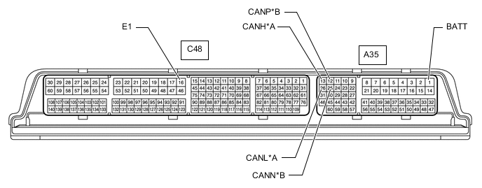
*A V Bus *B Sub Bus 15
-
Disconnect the ECM connectors.
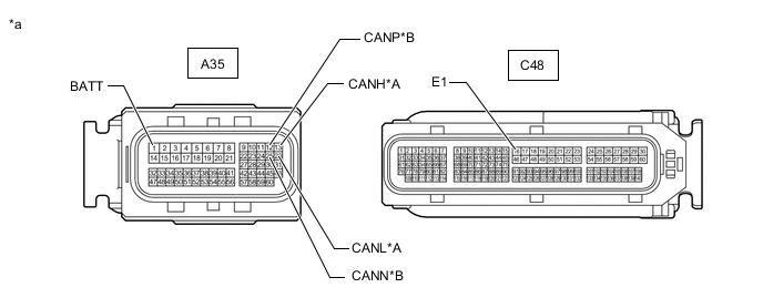
*A V Bus *B Sub Bus 15 *a Front view of wire harness connector
(to ECM)
- - -
Measure the resistance according to the value(s) in the table below.
V Bus Terminal No. (Symbol) Wiring Color Terminal Description Condition Specified Condition A35-13 (CANH) - A35-26 (CANL) Y - W HIGH-level CAN bus wire - LOW-level CAN bus wire Cable disconnected from negative (-) auxiliary battery terminal 108 to 132 Ω A35-13 (CANH) - C48-16 (E1) Y - BR HIGH-level CAN bus wire - GND Cable disconnected from negative (-) auxiliary battery terminal 200 Ω or higher A35-26 (CANL) - C48-16 (E1) W - BR LOW-level CAN bus wire - GND Cable disconnected from negative (-) auxiliary battery terminal 200 Ω or higher A35-13 (CANH) - A35-1 (BATT) Y - V HIGH-level CAN bus wire - Auxiliary battery positive (+) Cable disconnected from negative (-) auxiliary battery terminal 6 kΩ or higher A35-26 (CANL) - A35-1 (BATT) W - V LOW-level CAN bus wire - Auxiliary battery positive (+) Cable disconnected from negative (-) auxiliary battery terminal 6 kΩ or higher Sub Bus 15 Terminal No. (Symbol) Wiring Color Terminal Description Condition Specified Condition A35-12 (CANP) - A35-25 (CANN) R - W HIGH-level CAN bus wire - LOW-level CAN bus wire Cable disconnected from negative (-) auxiliary battery terminal 108 to 132 Ω A35-12 (CANP) - C48-16 (E1) R - BR HIGH-level CAN bus wire - GND Cable disconnected from negative (-) auxiliary battery terminal 200 Ω or higher A35-25 (CANN) - C48-16 (E1) W - BR LOW-level CAN bus wire - GND Cable disconnected from negative (-) auxiliary battery terminal 200 Ω or higher A35-12 (CANP) - A35-1 (BATT) R - V HIGH-level CAN bus wire - Auxiliary battery positive (+) Cable disconnected from negative (-) auxiliary battery terminal 6 kΩ or higher A35-25 (CANN) - A35-1 (BATT) W - V LOW-level CAN bus wire - Auxiliary battery positive (+) Cable disconnected from negative (-) auxiliary battery terminal 6 kΩ or higher
-
-
CHECK HYBRID VEHICLE CONTROL ECU
-
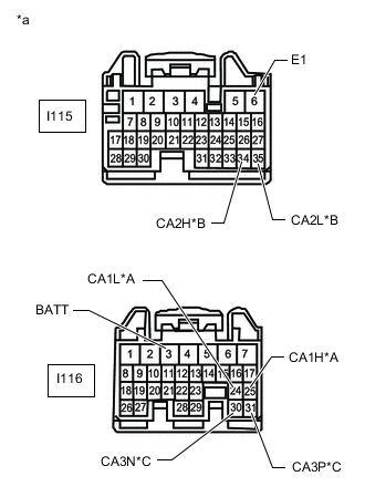
*A V Bus *B Sub Bus 11 *C Sub Bus 15 *a Front view of wire harness connector
(to Hybrid Vehicle Control ECU)
Disconnect the hybrid vehicle control ECU connectors.
-
Measure the resistance according to the value(s) in the table below.
V Bus Terminal No. (Symbol) Wiring Color Terminal Description Condition Specified Condition I116-25 (CA1H) - I116-24 (CA1L) LG - W HIGH-level CAN bus wire - LOW-level CAN bus wire Cable disconnected from negative (-) auxiliary battery terminal 54 to 69 Ω I116-25 (CA1H) - I115-6 (E1) LG - W-B HIGH-level CAN bus wire - GND Cable disconnected from negative (-) auxiliary battery terminal 200 Ω or higher I116-24 (CA1L) - I115-6 (E1) W - W-B LOW-level CAN bus wire - GND Cable disconnected from negative (-) auxiliary battery terminal 200 Ω or higher I116-25 (CA1H) - I116-3 (BATT) LG - R HIGH-level CAN bus wire - Auxiliary battery positive (+) Cable disconnected from negative (-) auxiliary battery terminal 6 kΩ or higher I116-24 (CA1L) - I116-3 (BATT) W - R LOW-level CAN bus wire - Auxiliary battery positive (+) Cable disconnected from negative (-) auxiliary battery terminal 6 kΩ or higher Sub Bus 11 Terminal No. (Symbol) Wiring Color Terminal Description Condition Specified Condition I115-34 (CA2H) - I115-35 (CA2L) P - W HIGH-level CAN bus wire - LOW-level CAN bus wire Cable disconnected from negative (-) auxiliary battery terminal 108 to 132 Ω I115-34 (CA2H) - I115-6 (E1) P - W-B HIGH-level CAN bus wire - GND Cable disconnected from negative (-) auxiliary battery terminal 200 Ω or higher I115-35 (CA2L) - I115-6 (E1) W - W-B LOW-level CAN bus wire - GND Cable disconnected from negative (-) auxiliary battery terminal 200 Ω or higher I115-34 (CA2H) - I116-3 (BATT) P - R HIGH-level CAN bus wire - Auxiliary battery positive (+) Cable disconnected from negative (-) auxiliary battery terminal 6 kΩ or higher I115-35 (CA2L) - I116-3 (BATT) W - R LOW-level CAN bus wire - Auxiliary battery positive (+) Cable disconnected from negative (-) auxiliary battery terminal 6 kΩ or higher Sub Bus 15 Terminal No. (Symbol) Wiring Color Terminal Description Condition Specified Condition I116-31 (CA3P) - I116-30 (CA3N) V - LG HIGH-level CAN bus wire - LOW-level CAN bus wire Cable disconnected from negative (-) auxiliary battery terminal 108 to 132 Ω I116-31 (CA3P) - I115-6 (E1) V - W-B HIGH-level CAN bus wire - GND Cable disconnected from negative (-) auxiliary battery terminal 200 Ω or higher I116-30 (CA3N) - I115-6 (E1) LG - W-B LOW-level CAN bus wire - GND Cable disconnected from negative (-) auxiliary battery terminal 200 Ω or higher I116-31 (CA3P) - I116-3 (BATT) V - R HIGH-level CAN bus wire - Auxiliary battery positive (+) Cable disconnected from negative (-) auxiliary battery terminal 6 kΩ or higher I116-30 (CA3N) - I116-3 (BATT) LG - R LOW-level CAN bus wire - Auxiliary battery positive (+) Cable disconnected from negative (-) auxiliary battery terminal 6 kΩ or higher
-
-
CHECK MAIN BODY ECU (MULTIPLEX NETWORK BODY ECU) AND INSTRUMENT PANEL JUNCTION BLOCK ASSEMBLY
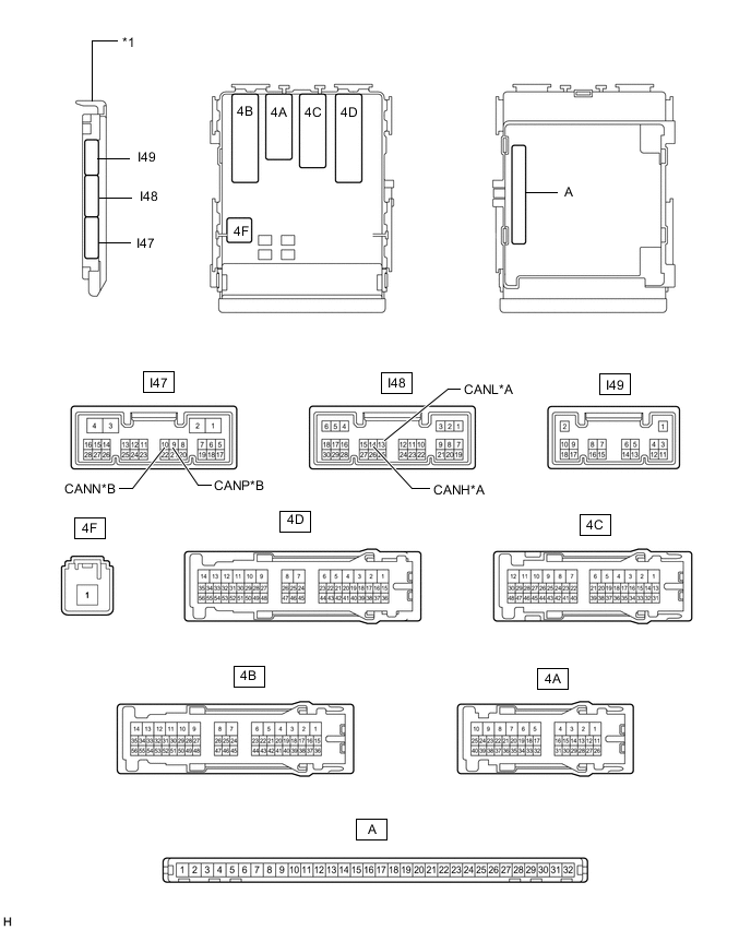
*A V Bus *B Sub Bus 1 *1 Main Body ECU (Multiplex Network Body ECU) - -
-
Remove the main body ECU (multiplex network body ECU).
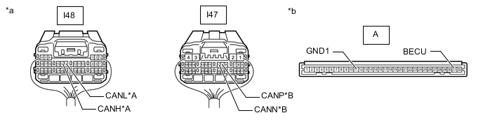
*A V Bus *B Sub Bus 1 *a Rear view of wire harness connector
(to Main Body ECU [Multiplex Network Body ECU])
*b Front view of wire harness connector
(to Main Body ECU [Multiplex Network Body ECU])
-
Reconnect the instrument panel junction block assembly connectors.
-
Measure the resistance according to the value(s) in the table below.
V Bus Terminal No. (Symbol) Wiring Color Terminal Description Condition Specified Condition I48-14 (CANH) - I48-13 (CANL) Y - W HIGH-level CAN bus wire - LOW-level CAN bus wire Cable disconnected from negative (-) auxiliary battery terminal 54 to 69 Ω I48-14 (CANH) - A-11 (GND1) Y - None HIGH-level CAN bus wire - GND Cable disconnected from negative (-) auxiliary battery terminal 200 Ω or higher I48-13 (CANL) - A-11 (GND1) W - None LOW-level CAN bus wire - GND Cable disconnected from negative (-) auxiliary battery terminal 200 Ω or higher I48-14 (CANH) - A-31 (BECU) Y - None HIGH-level CAN bus wire - Auxiliary battery positive (+) Cable disconnected from negative (-) auxiliary battery terminal 6 kΩ or higher I48-13 (CANL) - A-31 (BECU) W - None LOW-level CAN bus wire - Auxiliary battery positive (+) Cable disconnected from negative (-) auxiliary battery terminal 6 kΩ or higher Sub Bus 1 Terminal No. (Symbol) Wiring Color Terminal Description Condition Specified Condition I47-9 (CANP) - I47-10 (CANN) B - W HIGH-level CAN bus wire - LOW-level CAN bus wire Cable disconnected from negative (-) auxiliary battery terminal 108 to 132 Ω I47-9 (CANP) - A-11 (GND1) B - None HIGH-level CAN bus wire - GND Cable disconnected from negative (-) auxiliary battery terminal 200 Ω or higher I47-10 (CANN) - A-11 (GND1) W - None LOW-level CAN bus wire - GND Cable disconnected from negative (-) auxiliary battery terminal 200 Ω or higher I47-9 (CANP) - A-31 (BECU) B - None HIGH-level CAN bus wire - Auxiliary battery positive (+) Cable disconnected from negative (-) auxiliary battery terminal 6 kΩ or higher I47-10 (CANN) - A-31 (BECU) W - None LOW-level CAN bus wire - Auxiliary battery positive (+) Cable disconnected from negative (-) auxiliary battery terminal 6 kΩ or higher
-
-
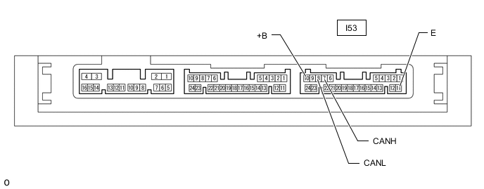
CHECK CERTIFICATION ECU (SMART KEY ECU ASSEMBLY)
-
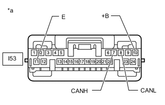
*a Front view of wire harness connector
(to Certification ECU [Smart Key ECU Assembly])
Disconnect the certification ECU (smart key ECU assembly) connector.
-
Measure the resistance according to the value(s) in the table below.
Terminal No. (Symbol) Wiring Color Terminal Description Condition Specified Condition I53-7 (CANH) - I53-8 (CANL) R - W HIGH-level CAN bus wire - LOW-level CAN bus wire Cable disconnected from negative (-) auxiliary battery terminal 54 to 69 Ω I53-7 (CANH) - I53-11 (E) R - W-B HIGH-level CAN bus wire - GND Cable disconnected from negative (-) auxiliary battery terminal 200 Ω or higher I53-8 (CANL) - I53-11 (E) W - W-B LOW-level CAN bus wire - GND Cable disconnected from negative (-) auxiliary battery terminal 200 Ω or higher I53-7 (CANH) - I53-10 (+B) R - W HIGH-level CAN bus wire - Auxiliary battery positive (+) Cable disconnected from negative (-) auxiliary battery terminal 6 kΩ or higher I53-8 (CANL) - I53-10 (+B) W - W LOW-level CAN bus wire - Auxiliary battery positive (+) Cable disconnected from negative (-) auxiliary battery terminal 6 kΩ or higher
-
-
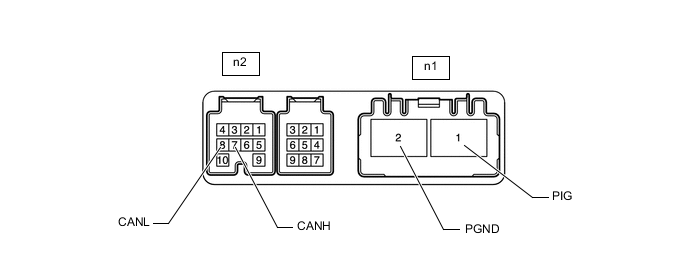
CHECK POWER STEERING ECU ASSEMBLY (for Power Tilt and Power Telescopic Steering Column)
-
*a Front view of wire harness connector
(to Power Steering ECU Assembly)
Disconnect the power steering ECU assembly connectors.
-
Measure the resistance according to the value(s) in the table below.
Terminal No. (Symbol) Wiring Color Terminal Description Condition Specified Condition n2-7 (CANH) - n2-8 (CANL) W - B HIGH-level CAN bus wire - LOW-level CAN bus wire Cable disconnected from negative (-) auxiliary battery terminal 54 to 69 Ω n2-7 (CANH) - n1-2 (PGND) W - B HIGH-level CAN bus wire - GND Cable disconnected from negative (-) auxiliary battery terminal 200 Ω or higher n2-8 (CANL) - n1-2 (PGND) B - B LOW-level CAN bus wire - GND Cable disconnected from negative (-) auxiliary battery terminal 200 Ω or higher n2-7 (CANH) - n1-1 (PIG) W - R HIGH-level CAN bus wire - Auxiliary battery positive (+) Cable disconnected from negative (-) auxiliary battery terminal 6 kΩ or higher n2-8 (CANL) - n1-1 (PIG) B - R LOW-level CAN bus wire - Auxiliary battery positive (+) Cable disconnected from negative (-) auxiliary battery terminal 6 kΩ or higher
-
-
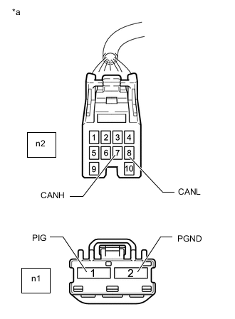
CHECK POWER STEERING ECU ASSEMBLY (for Manual Tilt and Manual Telescopic Steering Column)
-
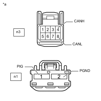
*a Front view of wire harness connector
(to Power Steering ECU Assembly)
Disconnect the power steering ECU assembly connectors.
-
Measure the resistance according to the value(s) in the table below.
Terminal No. (Symbol) Wiring Color Terminal Description Condition Specified Condition n3-4 (CANH) - n3-8 (CANL) W - B HIGH-level CAN bus wire - LOW-level CAN bus wire Cable disconnected from negative (-) auxiliary battery terminal 54 to 69 Ω n3-4 (CANH) - n1-2 (PGND) W - B HIGH-level CAN bus wire - GND Cable disconnected from negative (-) auxiliary battery terminal 200 Ω or higher n3-8 (CANL) - n1-2 (PGND) B - B LOW-level CAN bus wire - GND Cable disconnected from negative (-) auxiliary battery terminal 200 Ω or higher n3-4 (CANH) - n1-1 (PIG) W - R HIGH-level CAN bus wire - Auxiliary battery positive (+) Cable disconnected from negative (-) auxiliary battery terminal 6 kΩ or higher n3-8 (CANL) - n1-1 (PIG) B - R LOW-level CAN bus wire - Auxiliary battery positive (+) Cable disconnected from negative (-) auxiliary battery terminal 6 kΩ or higher
-
-
CHECK BRAKE BOOSTER WITH MASTER CYLINDER ASSEMBLY (SKID CONTROL ECU)
-
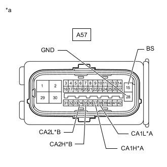
*A V Bus *B Sub Bus 15 *a Front view of wire harness connector
(to Brake Booster with Master Cylinder Assembly [Skid Control ECU])
Disconnect the brake booster with master cylinder assembly (skid control ECU) connector.
-
Measure the resistance according to the value(s) in the table below.
V Bus Terminal No. (Symbol) Wiring Color Terminal Description Condition Specified Condition A57-37 (CA1H) - A57-38 (CA1L) R - W HIGH-level CAN bus wire - LOW-level CAN bus wire Cable disconnected from negative (-) auxiliary battery terminal 54 to 69 Ω A57-37 (CA1H) - A57-28 (GND) R - W-B HIGH-level CAN bus wire - GND Cable disconnected from negative (-) auxiliary battery terminal 200 Ω or higher A57-38 (CA1L) - A57-28 (GND) W - W-B LOW-level CAN bus wire - GND Cable disconnected from negative (-) auxiliary battery terminal 200 Ω or higher A57-37 (CA1H) - A57-15 (BS) R - B HIGH-level CAN bus wire - Auxiliary battery positive (+) Cable disconnected from negative (-) auxiliary battery terminal 6 kΩ or higher A57-38 (CA1L) - A57-15 (BS) W - B LOW-level CAN bus wire - Auxiliary battery positive (+) Cable disconnected from negative (-) auxiliary battery terminal 6 kΩ or higher Sub Bus 15 Terminal No. (Symbol) Wiring Color Terminal Description Condition Specified Condition A57-35 (CA2H) - A57-34 (CA2L) B - W HIGH-level CAN bus wire - LOW-level CAN bus wire Cable disconnected from negative (-) auxiliary battery terminal 54 to 69 Ω A57-35 (CA2H) - A57-28 (GND) B - W-B HIGH-level CAN bus wire - GND Cable disconnected from negative (-) auxiliary battery terminal 200 Ω or higher A57-34 (CA2L) - A57-28 (GND) W - W-B LOW-level CAN bus wire - GND Cable disconnected from negative (-) auxiliary battery terminal 200 Ω or higher A57-35 (CA2H) - A57-15 (BS) B - B HIGH-level CAN bus wire - Auxiliary battery positive (+) Cable disconnected from negative (-) auxiliary battery terminal 6 kΩ or higher A57-34 (CA2L) - A57-15 (BS) W - B LOW-level CAN bus wire - Auxiliary battery positive (+) Cable disconnected from negative (-) auxiliary battery terminal 6 kΩ or higher
-
-
CHECK AIRBAG ECU ASSEMBLY
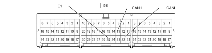
-
*a Front view of wire harness connector
(to Airbag ECU Assembly)
*b Front view of DLC3 Disconnect the airbag ECU assembly connector.
-
Measure the resistance according to the value(s) in the table below.
Terminal No. (Symbol) Wiring Color Terminal Description Condition Specified Condition I58-13 (CANH) - I58-22 (CANL) B - W HIGH-level CAN bus wire - LOW-level CAN bus wire Cable disconnected from negative (-) auxiliary battery terminal 54 to 69 Ω I58-13 (CANH) - I58-25 (E1) B - W-B HIGH-level CAN bus wire - GND Cable disconnected from negative (-) auxiliary battery terminal 200 Ω or higher I58-22 (CANL) - I58-25 (E1) W - W-B LOW-level CAN bus wire - GND Cable disconnected from negative (-) auxiliary battery terminal 200 Ω or higher I58-13 (CANH) - I7-16 (BAT) B - L HIGH-level CAN bus wire - Auxiliary battery positive (+) Cable disconnected from negative (-) auxiliary battery terminal 6 kΩ or higher I58-22 (CANL) - I7-16 (BAT) W - L LOW-level CAN bus wire - Auxiliary battery positive (+) Cable disconnected from negative (-) auxiliary battery terminal 6 kΩ or higher
-
-
CHECK SPIRAL WITH SENSOR CABLE SUB-ASSEMBLY (STEERING ANGLE SENSOR)
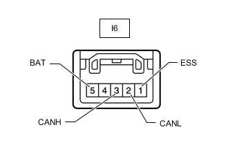
-

*a Front view of wire harness connector
(to Spiral with Sensor Cable Sub-assembly [Steering Angle Sensor])
Disconnect the spiral with sensor cable sub-assembly (steering angle sensor) connector.
-
Measure the resistance according to the value(s) in the table below.
Terminal No. (Symbol) Wiring Color Terminal Description Condition Specified Condition I6-3 (CANH) - I6-2 (CANL) P - W HIGH-level CAN bus wire - LOW-level CAN bus wire Cable disconnected from negative (-) auxiliary battery terminal 54 to 69 Ω I6-3 (CANH) - I6-1 (ESS) P - W-B HIGH-level CAN bus wire - GND Cable disconnected from negative (-) auxiliary battery terminal 200 Ω or higher I6-2 (CANL) - I6-1 (ESS) W - W-B LOW-level CAN bus wire - GND Cable disconnected from negative (-) auxiliary battery terminal 200 Ω or higher I6-3 (CANH) - I6-5 (BAT) P - SB HIGH-level CAN bus wire - Auxiliary battery positive (+) Cable disconnected from negative (-) auxiliary battery terminal 6 kΩ or higher I6-2 (CANL) - I6-5 (BAT) W - SB LOW-level CAN bus wire - Auxiliary battery positive (+) Cable disconnected from negative (-) auxiliary battery terminal 6 kΩ or higher
-
-
CHECK AIR CONDITIONING AMPLIFIER ASSEMBLY
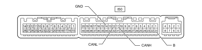
-
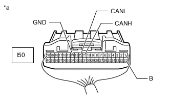
*a Rear view of wire harness connector
(to Air Conditioning Amplifier Assembly)
Disconnect the air conditioning amplifier assembly connector.
-
Measure the resistance according to the value(s) in the table below.
Terminal No. (Symbol) Wiring Color Terminal Description Condition Specified Condition I50-11 (CANH) - I50-12 (CANL) P - W HIGH-level CAN bus wire - LOW-level CAN bus wire Cable disconnected from negative (-) auxiliary battery terminal 54 to 69 Ω I50-11 (CANH) - I50-14 (GND) P - W-B HIGH-level CAN bus wire - GND Cable disconnected from negative (-) auxiliary battery terminal 200 Ω or higher I50-12 (CANL) - I50-14 (GND) W - W-B LOW-level CAN bus wire - GND Cable disconnected from negative (-) auxiliary battery terminal 200 Ω or higher I50-11 (CANH) - I50-21 (B) P - GR HIGH-level CAN bus wire - Auxiliary battery positive (+) Cable disconnected from negative (-) auxiliary battery terminal 6 kΩ or higher I50-12 (CANL) - I50-21 (B) W - GR LOW-level CAN bus wire - Auxiliary battery positive (+) Cable disconnected from negative (-) auxiliary battery terminal 6 kΩ or higher
-
-
CHECK RADIO RECEIVER ASSEMBLY (w/ Navigation System or Audio and Visual System [except 8 Speakers])
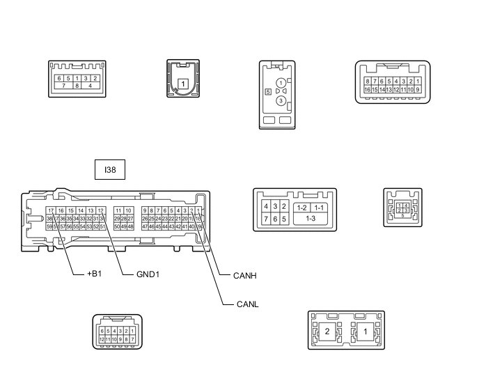
-
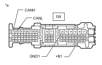
*a Front view of wire harness connector
(to Radio Receiver Assembly)
Disconnect the radio receiver assembly connector.
-
Measure the resistance according to the value(s) in the table below.
Terminal No. (Symbol) Wiring Color Terminal Description Condition Specified Condition I38-1 (CANH) - I38-2 (CANL) Y - W HIGH-level CAN bus wire - LOW-level CAN bus wire Cable disconnected from negative (-) auxiliary battery terminal 54 to 69 Ω I38-1 (CANH) - I38-12 (GND1) Y - W-B HIGH-level CAN bus wire - GND Cable disconnected from negative (-) auxiliary battery terminal 200 Ω or higher I38-2 (CANL) - I38-12 (GND1) W - W-B LOW-level CAN bus wire - GND Cable disconnected from negative (-) auxiliary battery terminal 200 Ω or higher I38-1 (CANH) - I38-17 (+B1) Y - P HIGH-level CAN bus wire - Auxiliary battery positive (+) Cable disconnected from negative (-) auxiliary battery terminal 6 kΩ or higher I38-2 (CANL) - I38-17 (+B1) W - P LOW-level CAN bus wire - Auxiliary battery positive (+) Cable disconnected from negative (-) auxiliary battery terminal 6 kΩ or higher
-
-
CHECK RADIO RECEIVER ASSEMBLY (w/ Audio and Visual System [for 8 Speakers])
-
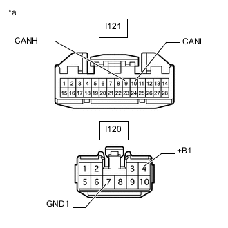
*a Front view of wire harness connector
(to Radio Receiver Assembly)
Disconnect the radio receiver assembly connectors.
-
Measure the resistance according to the value(s) in the table below.
Terminal No. (Symbol) Wiring Color Terminal Description Condition Specified Condition I121-9 (CANH) - I121-10 (CANL) Y - W HIGH-level CAN bus wire - LOW-level CAN bus wire Cable disconnected from negative (-) auxiliary battery terminal 54 to 69 Ω I121-9 (CANH) - I120-7 (GND1) Y - W-B HIGH-level CAN bus wire - GND Cable disconnected from negative (-) auxiliary battery terminal 200 Ω or higher I121-10 (CANL) - I120-7 (GND1) W - W-B LOW-level CAN bus wire - GND Cable disconnected from negative (-) auxiliary battery terminal 200 Ω or higher I121-9 (CANH) - I120-4 (+B1) Y - P HIGH-level CAN bus wire - Auxiliary battery positive (+) Cable disconnected from negative (-) auxiliary battery terminal 6 kΩ or higher I121-10 (CANL) - I120-4 (+B1) W - P LOW-level CAN bus wire - Auxiliary battery positive (+) Cable disconnected from negative (-) auxiliary battery terminal 6 kΩ or higher
-
-
CHECK COMBINATION METER ASSEMBLY
-
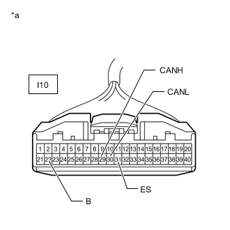
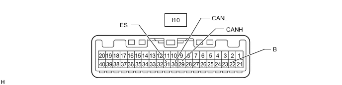
*a Front view of wire harness connector
(to Combination Meter Assembly)
Disconnect the combination meter assembly connector.
-
Measure the resistance according to the value(s) in the table below.
Terminal No. (Symbol) Wiring Color Terminal Description Condition Specified Condition I10-29 (CANH) - I10-30 (CANL) G - W HIGH-level CAN bus wire - LOW-level CAN bus wire Cable disconnected from negative (-) auxiliary battery terminal 108 to 132 Ω I10-29 (CANH) - I10-31 (ES) G - W-B HIGH-level CAN bus wire - GND Cable disconnected from negative (-) auxiliary battery terminal 200 Ω or higher I10-30 (CANL) - I10-31 (ES) W - W-B LOW-level CAN bus wire - GND Cable disconnected from negative (-) auxiliary battery terminal 200 Ω or higher I10-29 (CANH) - I10-22 (B) G - Y HIGH-level CAN bus wire - Auxiliary battery positive (+) Cable disconnected from negative (-) auxiliary battery terminal 6 kΩ or higher I10-30 (CANL) - I10-22 (B) W - Y LOW-level CAN bus wire - Auxiliary battery positive (+) Cable disconnected from negative (-) auxiliary battery terminal 6 kΩ or higher
-
-
CHECK PARKING BRAKE ECU ASSEMBLY
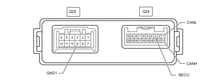
-
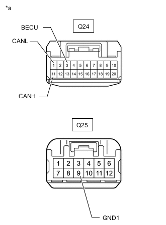
*a Front view of wire harness connector
(to Parking Brake ECU Assembly)
Disconnect the parking brake ECU assembly connectors.
-
Measure the resistance according to the value(s) in the table below.
Terminal No. (Symbol) Wiring Color Terminal Description Condition Specified Condition Q24-11 (CANH) - Q24-1 (CANL) B - W HIGH-level CAN bus wire - LOW-level CAN bus wire Cable disconnected from negative (-) auxiliary battery terminal 54 to 69 Ω Q24-11 (CANH) - Q25-9 (GND1) B - W-B HIGH-level CAN bus wire - GND Cable disconnected from negative (-) auxiliary battery terminal 200 Ω or higher Q24-1 (CANL) - Q25-9 (GND1) W - W-B LOW-level CAN bus wire - GND Cable disconnected from negative (-) auxiliary battery terminal 200 Ω or higher Q24-11 (CANH) - Q25-7 (+B) B - L HIGH-level CAN bus wire - Auxiliary battery positive (+) Cable disconnected from negative (-) auxiliary battery terminal 6 kΩ or higher Q24-1 (CANL) - Q25-7 (+B) W - L LOW-level CAN bus wire - Auxiliary battery positive (+) Cable disconnected from negative (-) auxiliary battery terminal 6 kΩ or higher
-
-
CHECK STEREO COMPONENT EQUALIZER ASSEMBLY (w/ ASC System)

-
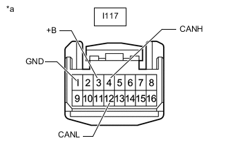
*a Front view of wire harness connector
(to Stereo Component Equalizer Assembly)
Disconnect the stereo component equalizer assembly connector.
-
Measure the resistance according to the value(s) in the table below.
Terminal No. (Symbol) Wiring Color Terminal Description Condition Specified Condition I117-4 (CANH) - I117-12 (CANL) R - W HIGH-level CAN bus wire - LOW-level CAN bus wire Cable disconnected from negative (-) auxiliary battery terminal 54 to 69 Ω I117-4 (CANH) - I117-1 (GND) R - W-B HIGH-level CAN bus wire - GND Cable disconnected from negative (-) auxiliary battery terminal 200 Ω or higher I117-12 (CANL) - I117-1 (GND) W - W-B LOW-level CAN bus wire - GND Cable disconnected from negative (-) auxiliary battery terminal 200 Ω or higher I117-4 (CANH) - I117-3 (+B) R - W HIGH-level CAN bus wire - Auxiliary battery positive (+) Cable disconnected from negative (-) auxiliary battery terminal 6 kΩ or higher I117-12 (CANL) - I117-3 (+B) W - W LOW-level CAN bus wire - Auxiliary battery positive (+) Cable disconnected from negative (-) auxiliary battery terminal 6 kΩ or higher
-
-
CHECK CLEARANCE WARNING ECU ASSEMBLY (w/ LEXUS Parking Assist-sensor System)
-
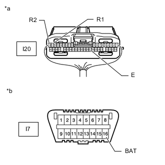
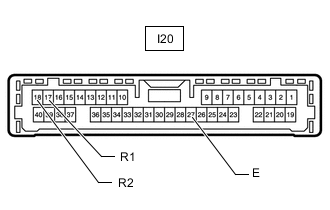
*a Rear view of wire harness connector
(to Clearance Warning ECU Assembly)
*b Front view of DLC3 Disconnect the clearance warning ECU assembly connector.
-
Measure the resistance according to the value(s) in the table below.
Terminal No. (Symbol) Wiring Color Terminal Description Condition Specified Condition I20-17 (R1) - I20-18 (R2) R - W HIGH-level CAN bus wire - LOW-level CAN bus wire Cable disconnected from negative (-) auxiliary battery terminal 54 to 69 Ω I20-17 (R1) - I20-27 (E) R - W-B HIGH-level CAN bus wire - GND Cable disconnected from negative (-) auxiliary battery terminal 200 Ω or higher I20-18 (R2) - I20-27 (E) W - W-B LOW-level CAN bus wire - GND Cable disconnected from negative (-) auxiliary battery terminal 200 Ω or higher I20-17 (R1) - I7-16 (BAT) R - L HIGH-level CAN bus wire - Auxiliary battery positive (+) Cable disconnected from negative (-) auxiliary battery terminal 6 kΩ or higher I20-18 (R2) - I7-16 (BAT) W - L LOW-level CAN bus wire - Auxiliary battery positive (+) Cable disconnected from negative (-) auxiliary battery terminal 6 kΩ or higher
-
-
CHECK DRIVING SUPPORT ECU ASSEMBLY (w/ Pre-crash Safety System)
-
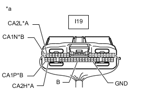
*A Sub Bus 11 *B Local Bus *a Rear view of wire harness connector
(to Driving Support ECU Assembly)
Disconnect the driving support ECU assembly connector.
-
Measure the resistance according to the value(s) in the table below.
Sub Bus 11 Terminal No. (Symbol) Wiring Color Terminal Description Condition Specified Condition I19-39 (CA2H) - I19-17 (CA2L) V - W HIGH-level CAN bus wire - LOW-level CAN bus wire Cable disconnected from negative (-) auxiliary battery terminal 54 to 69 Ω I19-39 (CA2H) - I19-25 (GND) V - W-B HIGH-level CAN bus wire - GND Cable disconnected from negative (-) auxiliary battery terminal 200 Ω or higher I19-17 (CA2L) - I19-25 (GND) W - W-B LOW-level CAN bus wire - GND Cable disconnected from negative (-) auxiliary battery terminal 200 Ω or higher I19-39 (CA2H) - I19-30 (B) V - Y HIGH-level CAN bus wire - Auxiliary battery positive (+) Cable disconnected from negative (-) auxiliary battery terminal 6 kΩ or higher I19-17 (CA2L) - I19-30 (B) W - Y LOW-level CAN bus wire - Auxiliary battery positive (+) Cable disconnected from negative (-) auxiliary battery terminal 6 kΩ or higher Local Bus Terminal No. (Symbol) Wiring Color Terminal Description Condition Specified Condition I19-40 (CA1P) - I19-18 (CA1N) L - B HIGH-level CAN bus wire - LOW-level CAN bus wire Cable disconnected from negative (-) auxiliary battery terminal 54 to 69 Ω I19-40 (CA1P) - I19-25 (GND) L - W-B HIGH-level CAN bus wire - GND Cable disconnected from negative (-) auxiliary battery terminal 200 Ω or higher I19-18 (CA1N) - I19-25 (GND) B - W-B LOW-level CAN bus wire - GND Cable disconnected from negative (-) auxiliary battery terminal 200 Ω or higher I19-40 (CA1P) - I19-30 (B) L - Y HIGH-level CAN bus wire - Auxiliary battery positive (+) Cable disconnected from negative (-) auxiliary battery terminal 6 kΩ or higher I19-18 (CA1N) - I19-30 (B) B - Y LOW-level CAN bus wire - Auxiliary battery positive (+) Cable disconnected from negative (-) auxiliary battery terminal 6 kΩ or higher
-
-
CHECK PARKING ASSIST ECU (w/ Panoramic View Monitor System)
-
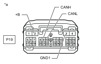
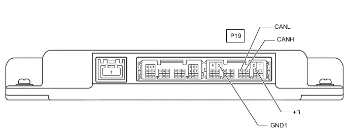
*a Front view of wire harness connector
(to Parking Assist ECU)
Disconnect the parking assist ECU connector.
-
Measure the resistance according to the value(s) in the table below.
Sub Bus 11 Terminal No. (Symbol) Wiring Color Terminal Description Condition Specified Condition P19-9 (CANH) - P19-10 (CANL) G - W HIGH-level CAN bus wire - LOW-level CAN bus wire Cable disconnected from negative (-) auxiliary battery terminal 54 to 69 Ω P19-9 (CANH) - P19-3 (GND1) G - W-B HIGH-level CAN bus wire - GND Cable disconnected from negative (-) auxiliary battery terminal 200 Ω or higher P19-10 (CANL) - P19-3 (GND1) W - W-B LOW-level CAN bus wire - GND Cable disconnected from negative (-) auxiliary battery terminal 200 Ω or higher P19-9 (CANH) - P19-2 (+B) G - L HIGH-level CAN bus wire - Auxiliary battery positive (+) Cable disconnected from negative (-) auxiliary battery terminal 6 kΩ or higher P19-10 (CANL) - P19-2 (+B) W - L LOW-level CAN bus wire - Auxiliary battery positive (+) Cable disconnected from negative (-) auxiliary battery terminal 6 kΩ or higher
-
-
CHECK ABSORBER CONTROL ECU (w/ Adaptive Variable Suspension System)
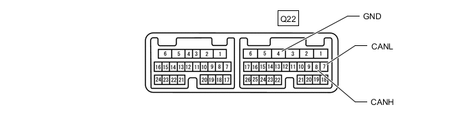
-
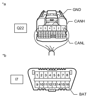
*a Rear view of wire harness connector
(to Absorber Control ECU)
*b Front view of DLC3 Disconnect the absorber control ECU connector.
-
Measure the resistance according to the value(s) in the table below.
Terminal No. (Symbol) Wiring Color Terminal Description Condition Specified Condition Q22-8 (CANH) - Q22-7 (CANL) B - W HIGH-level CAN bus wire - LOW-level CAN bus wire Cable disconnected from negative (-) auxiliary battery terminal 54 to 69 Ω Q22-8 (CANH) - Q22-4 (GND) B - W-B HIGH-level CAN bus wire - GND Cable disconnected from negative (-) auxiliary battery terminal 200 Ω or higher Q22-7 (CANL) - Q22-4 (GND) W - W-B LOW-level CAN bus wire - GND Cable disconnected from negative (-) auxiliary battery terminal 200 Ω or higher Q22-8 (CANH) - I7-16 (BAT) B - L HIGH-level CAN bus wire - Auxiliary battery positive (+) Cable disconnected from negative (-) auxiliary battery terminal 6 kΩ or higher Q22-7 (CANL) - I7-16 (BAT) W - L LOW-level CAN bus wire - Auxiliary battery positive (+) Cable disconnected from negative (-) auxiliary battery terminal 6 kΩ or higher
-
-
CHECK LANE DEPARTURE WARNING CAMERA (w/ Lane Departure Alert System)
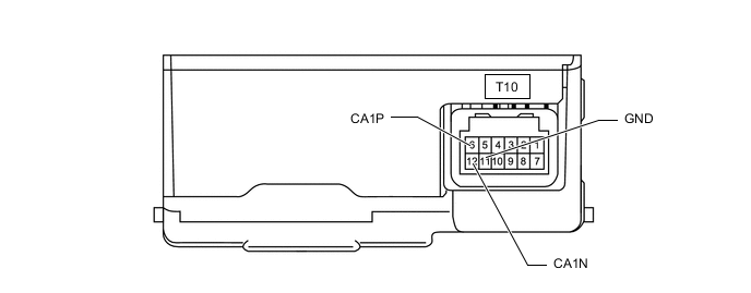
-
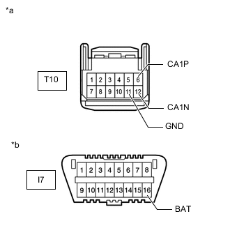
*a Front view of wire harness connector
(to Lane Departure Warning Camera)
*b Front view of DLC3 Disconnect the lane departure warning camera connector.
-
Measure the resistance according to the value(s) in the table below.
Terminal No. (Symbol) Wiring Color Terminal Description Condition Specified Condition T10-6 (CA1P) - T10-12 (CA1N) B - W HIGH-level CAN bus wire - LOW-level CAN bus wire Cable disconnected from negative (-) auxiliary battery terminal 54 to 69 Ω T10-6 (CA1P) - T10-11 (GND) B - W-B HIGH-level CAN bus wire - GND Cable disconnected from negative (-) auxiliary battery terminal 200 Ω or higher T10-12 (CA1N) - T10-11 (GND) W - W-B LOW-level CAN bus wire - GND Cable disconnected from negative (-) auxiliary battery terminal 200 Ω or higher T10-6 (CA1P) - I7-16 (BAT) B - L HIGH-level CAN bus wire - Auxiliary battery positive (+) Cable disconnected from negative (-) auxiliary battery terminal 6 kΩ or higher T10-12 (CA1N) - I7-16 (BAT) W - L LOW-level CAN bus wire - Auxiliary battery positive (+) Cable disconnected from negative (-) auxiliary battery terminal 6 kΩ or higher
-
-
CHECK BLIND SPOT MONITOR SENSOR LH (w/ Blind Spot Monitor System)

-
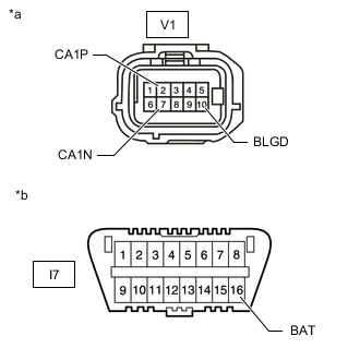
*a Front view of wire harness connector
(to Blind Spot Monitor Sensor LH)
*b Front view of DLC3 Disconnect the blind spot monitor sensor LH connector.
-
Measure the resistance according to the value(s) in the table below.
Terminal No. (Symbol) Wiring Color Terminal Description Condition Specified Condition V1-2 (CA1P) - V1-7 (CA1N) R - W HIGH-level CAN bus wire - LOW-level CAN bus wire Cable disconnected from negative (-) auxiliary battery terminal 54 to 69 Ω V1-2 (CA1P) - V1-10 (BLGD) R - W-B HIGH-level CAN bus wire - GND Cable disconnected from negative (-) auxiliary battery terminal 200 Ω or higher V1-7 (CA1N) - V1-10 (BLGD) W - W-B LOW-level CAN bus wire - GND Cable disconnected from negative (-) auxiliary battery terminal 200 Ω or higher V1-2 (CA1P) - I7-16 (BAT) R - L HIGH-level CAN bus wire - Auxiliary battery positive (+) Cable disconnected from negative (-) auxiliary battery terminal 6 kΩ or higher V1-7 (CA1N) - I7-16 (BAT) W - L LOW-level CAN bus wire - Auxiliary battery positive (+) Cable disconnected from negative (-) auxiliary battery terminal 6 kΩ or higher
-
-
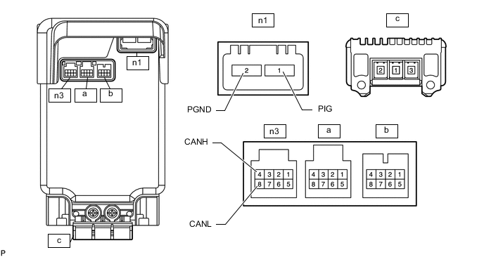
CHECK OUTER MIRROR CONTROL ECU ASSEMBLY RH (w/ Memory)

-
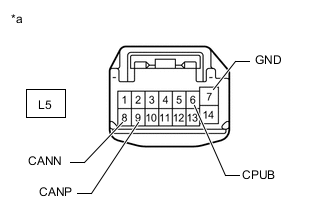
*a Front view of wire harness connector
(to Outer Mirror Control ECU Assembly RH)
Disconnect the outer mirror control ECU assembly RH connector.
-
Measure the resistance according to the value(s) in the table below.
Terminal No. (Symbol) Wiring Color Terminal Description Condition Specified Condition L5-9 (CANP) - L5-8 (CANN) R - W HIGH-level CAN bus wire - LOW-level CAN bus wire Cable disconnected from negative (-) auxiliary battery terminal 54 to 69 Ω L5-9 (CANP) - L5-7 (GND) R - W-B HIGH-level CAN bus wire - GND Cable disconnected from negative (-) auxiliary battery terminal 200 Ω or higher L5-8 (CANN) - L5-7 (GND) W - W-B LOW-level CAN bus wire - GND Cable disconnected from negative (-) auxiliary battery terminal 200 Ω or higher L5-9 (CANP) - L5-6 (CPUB) R - B HIGH-level CAN bus wire - Auxiliary battery positive (+) Cable disconnected from negative (-) auxiliary battery terminal 6 kΩ or higher L5-8 (CANN) - L5-6 (CPUB) W - B LOW-level CAN bus wire - Auxiliary battery positive (+) Cable disconnected from negative (-) auxiliary battery terminal 6 kΩ or higher
-
-
CHECK OUTER MIRROR CONTROL ECU ASSEMBLY LH (w/ Memory)

-

*a Front view of wire harness connector
(to Outer Mirror Control ECU Assembly LH)
Disconnect the outer mirror control ECU assembly LH connector.
-
Measure the resistance according to the value(s) in the table below.
Terminal No. (Symbol) Wiring Color Terminal Description Condition Specified Condition M5-9 (CANP) - M5-8 (CANN) B - W HIGH-level CAN bus wire - LOW-level CAN bus wire Cable disconnected from negative (-) auxiliary battery terminal 54 to 69 Ω M5-9 (CANP) - M5-7 (GND) B - W-B HIGH-level CAN bus wire - GND Cable disconnected from negative (-) auxiliary battery terminal 200 Ω or higher M5-8 (CANN) - M5-7 (GND) W - W-B LOW-level CAN bus wire - GND Cable disconnected from negative (-) auxiliary battery terminal 200 Ω or higher M5-9 (CANP) - M5-6 (CPUB) B - GR HIGH-level CAN bus wire - Auxiliary battery positive (+) Cable disconnected from negative (-) auxiliary battery terminal 6 kΩ or higher M5-8 (CANN) - M5-6 (CPUB) W - GR LOW-level CAN bus wire - Auxiliary battery positive (+) Cable disconnected from negative (-) auxiliary battery terminal 6 kΩ or higher
-
-
CHECK MULTIPLEX NETWORK DOOR ECU (w/ Power Back Door System)
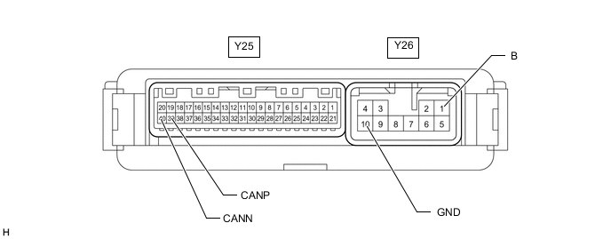
-
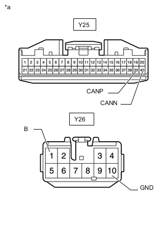
*a Front view of wire harness connector
(to Multiplex Network Door ECU)
Disconnect the multiplex network door ECU connectors.
-
Measure the resistance according to the value(s) in the table below.
Terminal No. (Symbol) Wiring Color Terminal Description Condition Specified Condition Y25-39 (CANP) - Y25-40 (CANN) G - W HIGH-level CAN bus wire - LOW-level CAN bus wire Cable disconnected from negative (-) auxiliary battery terminal 54 to 69 Ω Y25-39 (CANP) - Y26-10 (GND) G - W-B HIGH-level CAN bus wire - GND Cable disconnected from negative (-) auxiliary battery terminal 200 Ω or higher Y25-40 (CANN) - Y26-10 (GND) W - W-B LOW-level CAN bus wire - GND Cable disconnected from negative (-) auxiliary battery terminal 200 Ω or higher Y25-39 (CANP) - Y26-1 (B) G - LA-W HIGH-level CAN bus wire - Auxiliary battery positive (+) Cable disconnected from negative (-) auxiliary battery terminal 6 kΩ or higher Y25-40 (CANN) - Y26-1 (B) W - LA-W LOW-level CAN bus wire - Auxiliary battery positive (+) Cable disconnected from negative (-) auxiliary battery terminal 6 kΩ or higher
-
-
CHECK FRONT POWER SEAT SWITCH RH (w/ Memory)
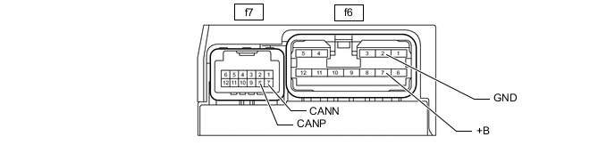
-
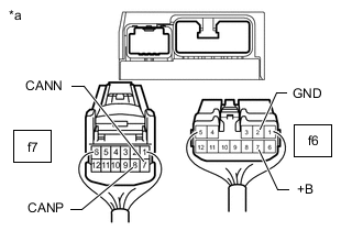
*a Rear view of wire harness connector
(to Front Power Seat Switch RH)
Disconnect the front power seat switch RH connectors.
-
Measure the resistance according to the value(s) in the table below.
Terminal No. (Symbol) Wiring Color Terminal Description Condition Specified Condition f7-8 (CANP) - f7-7 (CANN) L - W HIGH-level CAN bus wire - LOW-level CAN bus wire Cable disconnected from negative (-) auxiliary battery terminal 54 to 69 Ω f7-8 (CANP) - f6-2 (GND) L - W-B HIGH-level CAN bus wire - GND Cable disconnected from negative (-) auxiliary battery terminal 200 Ω or higher f7-7 (CANN) - f6-2 (GND) W - W-B LOW-level CAN bus wire - GND Cable disconnected from negative (-) auxiliary battery terminal 200 Ω or higher f7-8 (CANP) - f6-7 (+B) L - W HIGH-level CAN bus wire - Auxiliary battery positive (+) Cable disconnected from negative (-) auxiliary battery terminal 6 kΩ or higher f7-7 (CANN) - f6-7 (+B) W - W LOW-level CAN bus wire - Auxiliary battery positive (+) Cable disconnected from negative (-) auxiliary battery terminal 6 kΩ or higher
-
-
CHECK MULTIPLEX TILT AND TELESCOPIC ECU (for Power Tilt and Power Telescopic Steering Column)

-
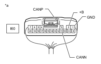
*a Rear view of wire harness connector
(to Multiplex Tilt and Telescopic ECU)
Disconnect the multiplex tilt and telescopic ECU connector.
-
Measure the resistance according to the value(s) in the table below.
Terminal No. (Symbol) Wiring Color Terminal Description Condition Specified Condition I60-3 (CANP) - I60-11 (CANN) G - W HIGH-level CAN bus wire - LOW-level CAN bus wire Cable disconnected from negative (-) auxiliary battery terminal 54 to 69 Ω I60-3 (CANP) - I60-1 (GND) G - W-B HIGH-level CAN bus wire - GND Cable disconnected from negative (-) auxiliary battery terminal 200 Ω or higher I60-11 (CANN) - I60-1 (GND) W - W-B LOW-level CAN bus wire - GND Cable disconnected from negative (-) auxiliary battery terminal 200 Ω or higher I60-3 (CANP) - I60-2 (+B) G - Y HIGH-level CAN bus wire - Auxiliary battery positive (+) Cable disconnected from negative (-) auxiliary battery terminal 6 kΩ or higher I60-11 (CANN) - I60-2 (+B) W - Y LOW-level CAN bus wire - Auxiliary battery positive (+) Cable disconnected from negative (-) auxiliary battery terminal 6 kΩ or higher
-
-
CHECK HEADLIGHT LIGHT CONTROL ECU SUB-ASSEMBLY LH

-
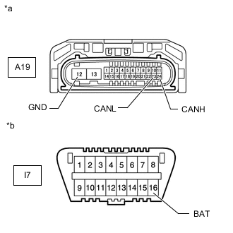
*a Front view of wire harness connector
(to Headlight Light Control ECU Sub-assembly LH)
*b Front view of DLC3 Disconnect the headlight light control ECU sub-assembly LH connector.
-
Measure the resistance according to the value(s) in the table below.
Terminal No. (Symbol) Wiring Color Terminal Description Condition Specified Condition A19-24 (CANH) - A19-23 (CANL) B - W HIGH-level CAN bus wire - LOW-level CAN bus wire Cable disconnected from negative (-) auxiliary battery terminal 54 to 69 Ω A19-24 (CANH) - A19-12 (GND) B - W-B HIGH-level CAN bus wire - GND Cable disconnected from negative (-) auxiliary battery terminal 200 Ω or higher A19-23 (CANL) - A19-12 (GND) W - W-B LOW-level CAN bus wire - GND Cable disconnected from negative (-) auxiliary battery terminal 200 Ω or higher A19-24 (CANH) - I7-16 (BAT) B - L HIGH-level CAN bus wire - Auxiliary battery positive (+) Cable disconnected from negative (-) auxiliary battery terminal 6 kΩ or higher A19-23 (CANL) - I7-16 (BAT) W - L LOW-level CAN bus wire - Auxiliary battery positive (+) Cable disconnected from negative (-) auxiliary battery terminal 6 kΩ or higher
-
-
CHECK MILLIMETER WAVE RADAR SENSOR ASSEMBLY (w/ Pre-crash Safety System)
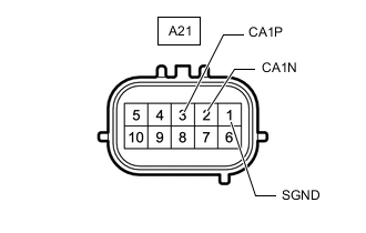
-
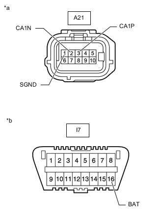
*a Front view of wire harness connector
(to Millimeter Wave Radar Sensor Assembly)
*b Front view of DLC3 Disconnect the millimeter wave radar sensor assembly connector.
-
Measure the resistance according to the value(s) in the table below.
Terminal No. (Symbol) Wiring Color Terminal Description Condition Specified Condition A21-3 (CA1P) - A21-2 (CA1N) L - B HIGH-level CAN bus wire - LOW-level CAN bus wire Cable disconnected from negative (-) auxiliary battery terminal 108 to 132 Ω A21-3 (CA1P) - A21-1 (SGND) L - B HIGH-level CAN bus wire - GND Cable disconnected from negative (-) auxiliary battery terminal 200 Ω or higher A21-2 (CA1N) - A21-1 (SGND) B - B LOW-level CAN bus wire - GND Cable disconnected from negative (-) auxiliary battery terminal 200 Ω or higher A21-3 (CA1P) - I7-16 (BAT) L - L HIGH-level CAN bus wire - Auxiliary battery positive (+) Cable disconnected from negative (-) auxiliary battery terminal 6 kΩ or higher A21-2 (CA1N) - I7-16 (BAT) B - L LOW-level CAN bus wire - Auxiliary battery positive (+) Cable disconnected from negative (-) auxiliary battery terminal 6 kΩ or higher
-