CAN COMMUNICATION SYSTEM(for LHD) ASC ECU Communication Stop Mode
DESCRIPTION
| Detection Item | Symptom | Trouble Area |
|---|---|---|
| ASC ECU Communication Stop Mode | Either condition is met:
|
|
For vehicles with an ASC System.
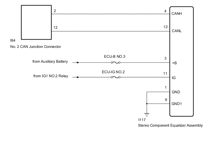
WIRING DIAGRAM
CAUTION / NOTICE / HINT
Note
-
Before measuring the resistance of the CAN bus, turn the power switch off and leave the vehicle for 1 minute or more without operating the key, switches or opening or closing the doors. After that, disconnect the cable from the negative (-) auxiliary battery terminal and leave the vehicle for 1 minute or more before measuring the resistance.
-
After turning the power switch off, waiting time may be required before disconnecting the cable from the negative (-) auxiliary battery terminal. Therefore, make sure to read the disconnecting the cable from the negative (-) auxiliary battery terminal notices before proceeding with work.
-
Because the order of diagnosis is important to allow correct diagnosis, make sure to begin troubleshooting using How to Proceed with Troubleshooting when CAN communication system related DTCs are output.
-
After performing repairs, perform the DTC check procedure and confirm that the DTCs are not output again.
-
DTC check procedure: Turn the power switch on (IG) and wait at least 8.2 seconds.
-
After the repair, perform the CAN bus check and check that all the ECUs and sensors connected to the CAN communication system are displayed.
-
Inspect the fuses for circuits related to this system before performing the following procedure.
PROCEDURE
-
CHECK FOR OPEN IN CAN BUS WIRE (STEREO COMPONENT EQUALIZER ASSEMBLY BRANCH WIRE)
-
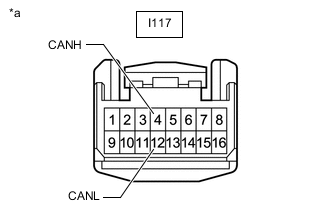
*a Front view of wire harness connector
(to Stereo Component Equalizer Assembly)
Disconnect the cable from the negative (-) auxiliary battery terminal.
-
Disconnect the stereo component equalizer assembly connector.
-
Measure the resistance according to the value(s) in the table below.
Standard Resistance Tester Connection Condition Specified Condition I117-4 (CANH) - I117-12 (CANL) Cable disconnected from negative (-) auxiliary battery terminal 54 to 69 Ω Result Proceed to OK NG
NG 
REPAIR OR REPLACE CAN BRANCH WIRE OR CONNECTOR (STEREO COMPONENT EQUALIZER ASSEMBLY)
OK 
-
-
CHECK HARNESS AND CONNECTOR (STEREO COMPONENT EQUALIZER ASSEMBLY - BATTERY AND BODY GROUND)
-
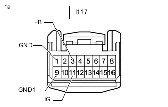
*a Front view of wire harness connector
(to Stereo Component Equalizer Assembly)
Reconnect the cable to the negative (-) auxiliary battery terminal.
Note
When disconnecting the cable, some systems need to be initialized after the cable is reconnected.
-
Measure the voltage according to the value(s) in the table below.
Standard Voltage Tester Connection Switch Condition Specified Condition I117-3 (+B) - Body ground Power switch off 11 to 14 V I117-11 (IG) - Body ground Power switch on (IG) 11 to 14 V -
Measure the resistance according to the value(s) in the table below.
Standard Resistance Tester Connection Condition Specified Condition I117-1 (GND) - Body ground Always Below 1 Ω I117-9 (GND1) - Body ground Always Below 1 Ω Result Proceed to OK NG
OK
REPLACE STEREO COMPONENT EQUALIZER ASSEMBLY Click here
NG
REPAIR OR REPLACE HARNESS OR CONNECTOR
-