CAN COMMUNICATION SYSTEM(for LHD) Short to B+ in CAN Bus Line
DESCRIPTION
There may be a short circuit between the CAN bus lines and +B when the resistance between terminals 6 (CANH) and 16 (BAT) or terminals 14 (CANL) and 16 (BAT) of the DLC3 is below 6 kΩ.
| Symptom | Trouble Area |
|---|---|
| The resistance between terminals 6 (CANH) and 16 (BAT) or terminals 14 (CANL) and 16 (BAT) of the DLC3 is below 6 kΩ. |
|
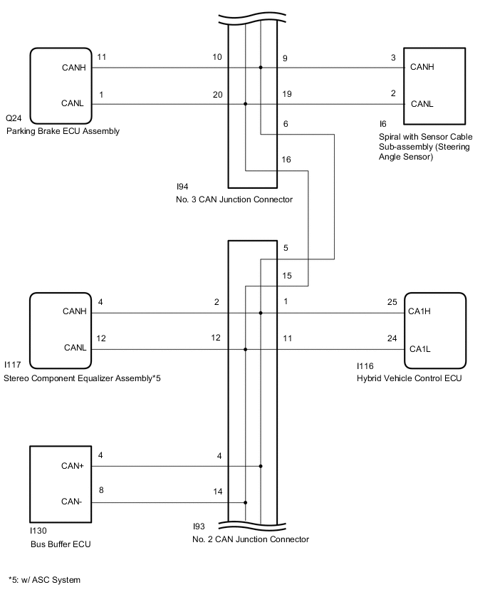
*2: w/ ASC System
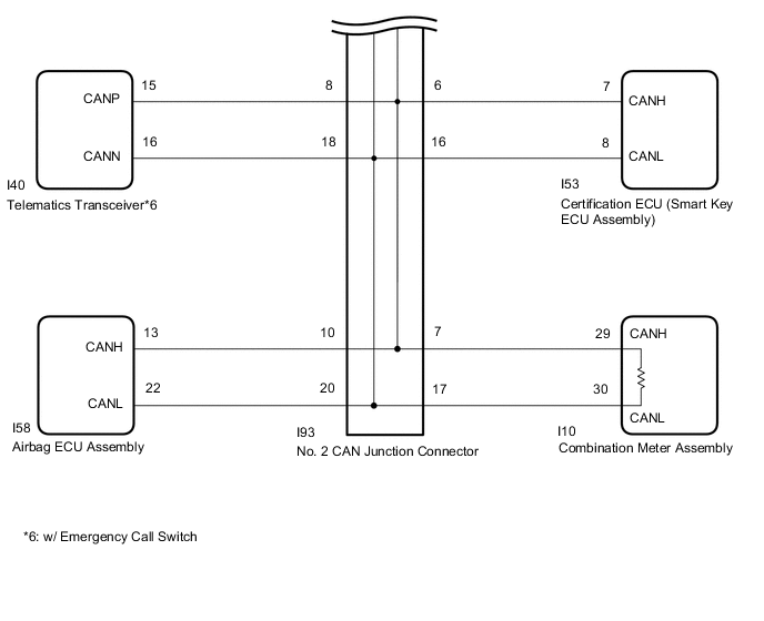
*3: w/ Emergency Call Switch
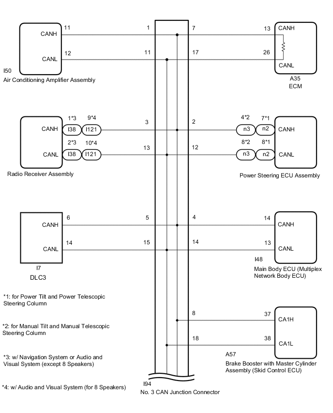
WIRING DIAGRAM
CAUTION / NOTICE / HINT
Note
-
Because the order of diagnosis is important to allow correct diagnosis, make sure to begin troubleshooting using How to Proceed with Troubleshooting when CAN communication system related DTCs are output.
-
Before measuring the resistance of the CAN bus, turn the power switch off and leave the vehicle for 1 minute or more without operating the key, switches or opening or closing the doors. After that, disconnect the cable from the negative (-) auxiliary battery terminal and leave the vehicle for 1 minute or more before measuring the resistance.
-
After turning the power switch off, waiting time may be required before disconnecting the cable from the auxiliary battery terminal. Therefore, make sure to read the disconnecting the cable from the auxiliary battery terminal notice before proceeding with work.
-
Before replacing the certification ECU (smart key ECU assembly), refer to the service bulletin.
-
Before replacing the main body ECU (multiplex network body ECU) is replaced, refer to the service bulletin.
-
The vehicle is equipped with an SRS (Supplemental Restraint System) which includes components such as airbags. Before servicing (including removal or installation of parts), be sure to read the Precaution in the SRS.
-
When replacing the combination meter assembly, make sure to replace it with a new one.
-
Depending on the parts that are replaced during vehicle inspection or maintenance, performing initialization, registration or calibration may be needed. Refer to Precaution for G-BOOK.
Tech Tips
-
Operating the power switch, any switches or any doors triggers related ECU and sensor communication with the CAN, which causes resistance variation.
-
Even after DTCs are cleared, if a DTC is stored again after driving the vehicle for a while, the malfunction may be occurring due to vibration of the vehicle. In such a case, wiggling the ECUs or wire harness while performing the inspection below may help determine the cause of the malfunction.
-
Connectors that connect to the CAN junction connector can be distinguished by the color of their CAN bus lines. When the connectors have been disconnected from the CAN junction connector, reconnecting the connectors to non-original positions on the CAN junction connector does not affect system performance. However, it is preferred to reconnect the connectors to their original positions to avoid negative effects on the wiring such as tension on the wiring harnesses, and to make future maintenance easier.
PROCEDURE
-
CHECK FOR SHORT TO B+ IN CAN BUS WIRE (DLC3 CAN BRANCH WIRE)
-
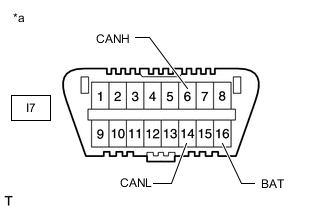
*a Front view of DLC3 Disconnect the cable from the negative (-) auxiliary battery terminal.
-
Disconnect the No. 3 CAN junction connector.
-
Measure the resistance according to the value(s) in the table below.
Standard Resistance Tester Connection Condition Specified Condition I7-6 (CANH) - I7-16 (BAT) Cable disconnected from negative (-) auxiliary battery terminal 6 kΩ or higher I7-14 (CANL) - I7-16 (BAT) Cable disconnected from negative (-) auxiliary battery terminal 6 kΩ or higher Result Proceed to OK NG
NG 
REPAIR OR REPLACE CAN BRANCH WIRE CONNECTED TO DLC3 (CANH, CANL)
OK 
-
-
CONNECT CONNECTOR
-
Reconnect the No. 3 CAN junction connector.
Result Proceed to NEXT
NEXT
-
-
CHECK FOR SHORT TO B+ IN CAN BUS WIRE (NO. 2 CAN JUNCTION CONNECTOR SIDE)
-
*a Front view of DLC3 Disconnect the No. 2 CAN junction connector.
-
Measure the resistance according to the value(s) in the table below.
Standard Resistance Tester Connection Condition Specified Condition I7-6 (CANH) - I7-16 (BAT) Cable disconnected from negative (-) auxiliary battery terminal 6 kΩ or higher I7-14 (CANL) - I7-16 (BAT) Cable disconnected from negative (-) auxiliary battery terminal 6 kΩ or higher Result Proceed to OK NG
NG 
CONNECT CONNECTOR Click here
OK
-
-
CHECK SHORT TO B+ IN CAN BUS WIRE (NO. 2 CAN JUNCTION CONNECTOR)
-
Disconnect the No. 2 CAN junction connector.
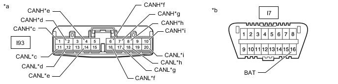
*a Front view of wire harness connector
(to No. 2 CAN Junction Connector)
*b Front view of DLC3 *c to Hybrid Vehicle Control ECU *d to Stereo Component Equalizer Assembly (w/ ASC System) *e to Bus Buffer ECU *f to Certification ECU (Smart Key ECU Assembly) *g to Combination Meter Assembly *h to Telematics Transceiver (w/ Emergency Call Switch) *i to Airbag ECU Assembly - - -
Measure the resistance according to the value(s) in the table below.
Standard Resistance *1: w/ ASC SystemTester Connection Condition Specified Condition Connected to I93-1 (CANH) - I7-16 (BAT) Cable disconnected from negative (-) auxiliary battery terminal 6 kΩ or higher Hybrid Vehicle Control ECU I93-11 (CANL) - I7-16 (BAT) Cable disconnected from negative (-) auxiliary battery terminal 6 kΩ or higher I93-2 (CANH) - I7-16 (BAT) Cable disconnected from negative (-) auxiliary battery terminal 6 kΩ or higher Stereo Component Equalizer Assembly*1 I93-12 (CANL) - I7-16 (BAT) Cable disconnected from negative (-) auxiliary battery terminal 6 kΩ or higher I93-4 (CANH) - I7-16 (BAT) Cable disconnected from negative (-) auxiliary battery terminal 6 kΩ or higher Bus Buffer ECU I93-14 (CANL) - I7-16 (BAT) Cable disconnected from negative (-) auxiliary battery terminal 6 kΩ or higher I93-6 (CANH) - I7-16 (BAT) Cable disconnected from negative (-) auxiliary battery terminal 6 kΩ or higher Certification ECU (Smart Key ECU Assembly) I93-16 (CANL) - I7-16 (BAT) Cable disconnected from negative (-) auxiliary battery terminal 6 kΩ or higher I93-7 (CANH) - I7-16 (BAT) Cable disconnected from negative (-) auxiliary battery terminal 6 kΩ or higher Combination Meter Assembly I93-17 (CANL) - I7-16 (BAT) Cable disconnected from negative (-) auxiliary battery terminal 6 kΩ or higher I93-8 (CANH) - I7-16 (BAT) Cable disconnected from negative (-) auxiliary battery terminal 6 kΩ or higher Telematics Transceiver*2 I93-18 (CANL) - I7-16 (BAT) Cable disconnected from negative (-) auxiliary battery terminal 6 kΩ or higher I93-10 (CANH) - I7-16 (BAT) Cable disconnected from negative (-) auxiliary battery terminal 6 kΩ or higher Airbag ECU Assembly I93-20 (CANL) - I7-16 (BAT) Cable disconnected from negative (-) auxiliary battery terminal 6 kΩ or higher
*2: w/ Emergency Call Switch
Result Result Proceed to OK A NG (to hybrid vehicle control ECU CAN branch wire) B NG (to stereo component equalizer assemblypower steering ECU assembly CAN branch wire) (w/ ASC System) C NG (to bus buffer ECU CAN branch wire) D NG (to certification ECU [smart key ECU assembly] CAN branch wire) E NG (to combination meter assembly CAN main wire) F NG (to telematics transceiver CAN branch wire) (w/ Emergency Call Switch) G NG (to airbag ECU assembly CAN branch wire) H
A
REPLACE NO. 2 CAN JUNCTION CONNECTOR
C
CONNECT CONNECTOR Click here
D
CONNECT CONNECTOR Click here
E
CONNECT CONNECTOR Click here
F
CONNECT CONNECTOR Click here
G
CONNECT CONNECTOR Click here
H
CONNECT CONNECTOR Click here
B
-
-
CONNECT CONNECTOR
-
Reconnect the No. 3 CAN junction connector.
Result Proceed to NEXT
NEXT
-
-
CHECK FOR SHORT TO B+ IN CAN BUS WIRE (HYBRID VEHICLE CONTROL ECU BRANCH WIRE)
-
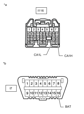
*a Front view of wire harness connector
(to Hybrid Vehicle Control ECU)
*b Front view of DLC3 Disconnect the hybrid vehicle control ECU connector.
-
Measure the resistance according to the value(s) in the table below.
Standard Resistance Tester Connection Condition Specified Value I116-25 (CA1H) - I7-16 (BAT) Cable disconnected from negative (-) auxiliary battery terminal 6 kΩ or higher I116-24 (CA1L) - I7-16 (BAT) Cable disconnected from negative (-) auxiliary battery terminal 6 kΩ or higher Result Proceed to OK NG
OK
REPLACE HYBRID VEHICLE CONTROL ECU Click here
NG
REPAIR OR REPLACE CAN BRANCH WIRE CONNECTED TO HYBRID VEHICLE CONTROL ECU (CA1H, CA1L)
-
-
CONNECT CONNECTOR
-
Reconnect the No. 3 CAN junction connector.
Result Proceed to NEXT
NEXT
-
-
CHECK FOR SHORT TO B+ IN CAN BUS WIRE (STEREO COMPONENT EQUALIZER ASSEMBLY BRANCH WIRE)
-
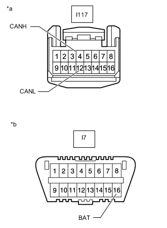
*a Front view of wire harness connector
(to Stereo Component Equalizer Assembly)
*b Front view of DLC3 Disconnect the stereo component equalizer assembly connector.
-
Measure the resistance according to the value(s) in the table below.
Standard Resistance Tester Connection Condition Specified Condition I117-4 (CANH) - I7-16 (BAT) Cable disconnected from negative (-) auxiliary battery terminal 6 kΩ or higher I117-12 (CANL) - I7-16 (BAT) Cable disconnected from negative (-) auxiliary battery terminal 6 kΩ or higher Result Proceed to OK NG
OK
REPLACE STEREO COMPONENT EQUALIZER ASSEMBLY Click here
NG
REPAIR OR REPLACE CAN BRANCH WIRE CONNECTED TO STEREO COMPONENT EQUALIZER ASSEMBLY (CANH, CANL)
-
-
CONNECT CONNECTOR
-
Reconnect the No. 3 CAN junction connector.
Result Proceed to NEXT
NEXT
-
-
CHECK FOR SHORT TO B+ IN CAN BUS WIRE (BUS BUFFER ECU BRANCH WIRE)
-
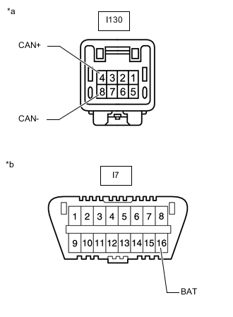
*a Front view of wire harness connector
(to Bus Buffer ECU)
*b Front view of DLC3 Disconnect the bus buffer ECU connector.
-
Measure the resistance according to the value(s) in the table below.
Standard Resistance Tester Connection Condition Specified Condition I130-4 (CAN+) - I7-16 (BAT) Cable disconnected from negative (-) auxiliary battery terminal 6 kΩ or higher I130-8 (CAN-) - I7-16 (BAT) Cable disconnected from negative (-) auxiliary battery terminal 6 kΩ or higher Result Proceed to OK NG
OK
REPLACE BUS BUFFER ECU
NG
REPAIR OR REPLACE CAN BRANCH WIRE CONNECTED TO BUS BUFFER ECU (CAN+, CAN-)
-
-
CONNECT CONNECTOR
-
Reconnect the No. 2 CAN junction connector.
Result Proceed to NEXT
NEXT
-
-
CHECK FOR SHORT TO B+ IN CAN BUS WIRE (CERTIFICATION ECU BRANCH WIRE)
-
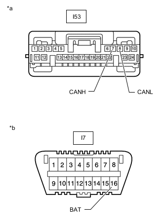
*a Front view of wire harness connector
(to Certification ECU [Smart Key ECU Assembly])
*b Front view of DLC3 Disconnect the certification ECU (smart key ECU assembly) connector.
-
Measure the resistance according to the value(s) in the table below.
Standard Resistance Tester Connection Condition Specified Condition I53-7 (CANH) - I7-16 (BAT) Cable disconnected from negative (-) auxiliary battery terminal 6 kΩ or higher I53-8 (CANL) - I7-16 (BAT) Cable disconnected from negative (-) auxiliary battery terminal 6 kΩ or higher Result Proceed to OK NG
OK
REPLACE CERTIFICATION ECU (SMART KEY ECU ASSEMBLY)
NG
REPAIR OR REPLACE CAN BRANCH WIRE CONNECTED TO CERTIFICATION ECU (CANH, CANL)
-
-
CONNECT CONNECTOR
-
Reconnect the No. 2 CAN junction connector.
Result Proceed to NEXT
NEXT
-
-
CHECK FOR SHORT TO B+ IN CAN BUS WIRE (COMBINATION METER ASSEMBLY MAIN WIRE)
-
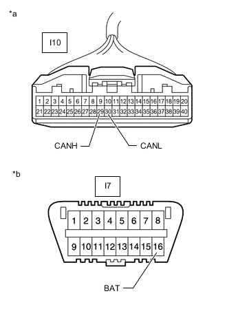
*a Front view of wire harness connector
(to Combination Meter Assembly)
*b Front view of DLC3 Disconnect the combination meter assembly connector.
-
Measure the resistance according to the value(s) in the table below.
Standard Resistance Tester Connection Condition Specified Condition I10-29 (CANH) - I7-16 (BAT) Cable disconnected from negative (-) auxiliary battery terminal 6 kΩ or higher I10-30 (CANL) - I7-16 (BAT) Cable disconnected from negative (-) auxiliary battery terminal 6 kΩ or higher Result Proceed to OK NG
OK
REPLACE COMBINATION METER ASSEMBLY Click here
NG
REPAIR OR REPLACE CAN MAIN WIRE CONNECTED TO COMBINATION METER ASSEMBLY (CANH, CANL)
-
-
CONNECT CONNECTOR
-
Reconnect the No. 3 CAN junction connector.
Result Proceed to NEXT
NEXT
-
-
CHECK FOR SHORT TO B+ IN CAN BUS WIRE (TELEMATICS TRANSCEIVER BRANCH WIRE)
-
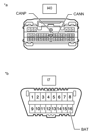
*a Front view of wire harness connector
(to Telematics Transceiver)
*b Front view of DLC3 Disconnect the telematics transceiver connector.
-
Measure the resistance according to the value(s) in the table below.
Standard Resistance Tester Connection Condition Specified Condition I40-15 (CANP) - I7-16 (BAT) Cable disconnected from negative (-) auxiliary battery terminal 6 kΩ or higher I40-16 (CANN) - I7-16 (BAT) Cable disconnected from negative (-) auxiliary battery terminal 6 kΩ or higher Result Proceed to OK NG
OK
REPLACE TELEMATICS TRANSCEIVER Click here
NG
REPAIR OR REPLACE CAN BRANCH WIRE CONNECTED TO TELEMATICS TRANSCEIVER (CANP, CANN)
-
-
CONNECT CONNECTOR
-
Reconnect the No. 2 CAN junction connector.
Result Proceed to NEXT
NEXT
-
-
CHECK FOR SHORT TO B+ IN CAN BUS WIRE (AIRBAG ECU ASSEMBLY BRANCH WIRE)
-
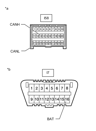
*a Front view of wire harness connector
(to Airbag ECU Assembly)
*b Front view of DLC3 Disconnect the airbag ECU assembly connector.
-
Measure the resistance according to the value(s) in the table below.
Standard Resistance Tester Connection Condition Specified Condition I58-13 (CANH) - I7-16 (BAT) Cable disconnected from negative (-) auxiliary battery terminal 6 kΩ or higher I58-22 (CANL) - I7-16 (BAT) Cable disconnected from negative (-) auxiliary battery terminal 6 kΩ or higher Result Proceed to OK NG
OK
REPLACE AIRBAG ECU ASSEMBLY Click here
NG
REPAIR OR REPLACE CAN BRANCH WIRE CONNECTED TO AIRBAG ECU ASSEMBLY (CANH, CANL)
-
-
CONNECT CONNECTOR
-
Reconnect the No. 2 CAN junction connector.
Result Proceed to NEXT
NEXT
-
-
CHECK FOR SHORT TO B+ IN CAN BUS WIRE (NO. 3 CAN JUNCTION CONNECTOR)
-
Reconnect the No. 3 CAN junction connector.
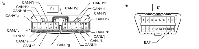
*a Front view of wire harness connector
(to No. 3 CAN Junction Connector)
*b Front view of DLC3 *c to Air Conditioning Amplifier Assembly *d to Power Steering ECU Assembly *e to Radio Receiver Assembly (w/ Navigation System or Audio and Visual System) *f to Main Body ECU (Multiplex Network Body ECU) *g to No. 2 CAN Junction Connector *h to ECM *i to Brake Booster with Master Cylinder Assembly (Skid Control ECU) *j to Spiral with Sensor Cable Sub-assembly (Steering Angle Sensor) *k to Parking Brake ECU Assembly - - -
Measure the resistance according to the value(s) in the table below.
Standard Resistance *: w/ Navigation System or Audio and Visual SystemTester Connection Condition Specified Condition Connected to I94-1 (CANH) - I7-16 (BAT) Cable disconnected from negative (-) auxiliary battery terminal 6 kΩ or higher Air Conditioning Amplifier Assembly I94-11 (CANL) - I7-16 (BAT) Cable disconnected from negative (-) auxiliary battery terminal 6 kΩ or higher I94-2 (CANH) - I7-16 (BAT) Cable disconnected from negative (-) auxiliary battery terminal 6 kΩ or higher Power Steering ECU Assembly I94-12 (CANL) - I7-16 (BAT) Cable disconnected from negative (-) auxiliary battery terminal 6 kΩ or higher I94-3 (CANH) - I7-16 (BAT) Cable disconnected from negative (-) auxiliary battery terminal 6 kΩ or higher Radio Receiver Assembly* I94-13 (CANL) - I7-16 (BAT) Cable disconnected from negative (-) auxiliary battery terminal 6 kΩ or higher I94-4 (CANH) - I7-16 (BAT) Cable disconnected from negative (-) auxiliary battery terminal 6 kΩ or higher Main Body ECU (Multiplex Network Body ECU) I94-14 (CANL) - I7-16 (BAT) Cable disconnected from negative (-) auxiliary battery terminal 6 kΩ or higher I94-6 (CANH) - I7-16 (BAT) Cable disconnected from negative (-) auxiliary battery terminal 6 kΩ or higher No. 2 CAN Junction Connector I94-16 (CANL) - I7-16 (BAT) Cable disconnected from negative (-) auxiliary battery terminal 6 kΩ or higher I94-7 (CANH) - I7-16 (BAT) Cable disconnected from negative (-) auxiliary battery terminal 6 kΩ or higher ECM I94-17 (CANL) - I7-16 (BAT) Cable disconnected from negative (-) auxiliary battery terminal 6 kΩ or higher I94-8 (CANH) - I7-16 (BAT) Cable disconnected from negative (-) auxiliary battery terminal 6 kΩ or higher Brake Booster with Master Cylinder Assembly (Skid Control ECU) I94-18 (CANL) - I7-16 (BAT) Cable disconnected from negative (-) auxiliary battery terminal 6 kΩ or higher I94-9 (CANH) - I7-16 (BAT) Cable disconnected from negative (-) auxiliary battery terminal 6 kΩ or higher Spiral with Sensor Cable Sub-assembly (Steering Angle Sensor) I94-19 (CANL) - I7-16 (BAT) Cable disconnected from negative (-) auxiliary battery terminal 6 kΩ or higher I94-10 (CANH) - I7-16 (BAT) Cable disconnected from negative (-) auxiliary battery terminal 6 kΩ or higher Parking Brake ECU Assembly I94-20 (CANL) - I7-16 (BAT) Cable disconnected from negative (-) auxiliary battery terminal 6 kΩ or higher
Result Result Proceed to OK A NG (to air conditioning amplifier assembly CAN branch wire) B NG (to power steering ECU assembly CAN branch wire) (for Power Tilt and Power Telescopic Steering Column) C NG (to power steering ECU assembly CAN branch wire) (for Manual Tilt and Manual Telescopic Steering Column) D NG (to radio receiver assembly CAN branch wire) (w/ Navigation System or Audio and Visual System [except 8 Speakers]) E NG (to radio receiver assembly CAN branch wire) (w/ Audio and Visual System [for 8 Speakers]) F NG (to main body ECU [multiplex network body ECU] CAN branch wire) G NG (to ECM CAN main wire) H NG (to brake booster with master cylinder assembly [skid Control ECU] CAN branch wire) I NG (to spiral with sensor cable sub-assembly [steering angle sensor] CAN branch wire) J NG (to parking brake ECU assembly CAN branch wire) K NG (to No. 2 CAN junction connector CAN main wire) L
A
REPLACE NO. 3 CAN JUNCTION CONNECTOR
C
CONNECT CONNECTOR Click here
D
CONNECT CONNECTOR Click here
E
CONNECT CONNECTOR Click here
F
CONNECT CONNECTOR Click here
G
CONNECT CONNECTOR Click here
H
CONNECT CONNECTOR Click here
I
CONNECT CONNECTOR Click here
J
CONNECT CONNECTOR Click here
K
CONNECT CONNECTOR Click here
L
REPAIR OR REPLACE CAN MAIN WIRE OR CONNECTOR (NO. 2 CAN JUNCTION CONNECTOR - NO. 3 CAN JUNCTION CONNECTOR)
B
-
-
CONNECT CONNECTOR
-
Reconnect the No. 2 CAN junction connector.
Result Proceed to NEXT
NEXT
-
-
CHECK FOR SHORT TO B+ IN CAN BUS WIRE (AIR CONDITIONING AMPLIFIER ASSEMBLY BRANCH WIRE)
-
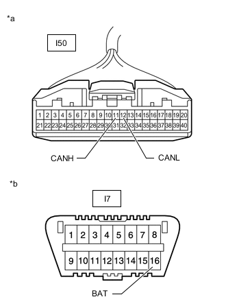
*a Front view of wire harness connector
(to Air Conditioning Amplifier Assembly)
*b Front view of DLC3 Disconnect the air conditioning amplifier assembly connector.
-
Measure the resistance according to the value(s) in the table below.
Standard Resistance Tester Connection Condition Specified Condition I50-11 (CANH) - I7-16 (BAT) Cable disconnected from negative (-) auxiliary battery terminal 6 kΩ or higher I50-12 (CANL) - I7-16 (BAT) Cable disconnected from negative (-) auxiliary battery terminal 6 kΩ or higher Result Proceed to OK NG
OK
REPLACE AIR CONDITIONING AMPLIFIER ASSEMBLY Click here
NG
REPAIR OR REPLACE CAN BRANCH WIRE CONNECTED TO AIR CONDITIONING AMPLIFIER ASSEMBLY (CANH, CANL)
-
-
CONNECT CONNECTOR
-
Reconnect the No. 2 CAN junction connector.
Result Proceed to NEXT
NEXT
-
-
CHECK FOR SHORT TO B+ IN CAN BUS WIRE (POWER STEERING ECU ASSEMBLY BRANCH WIRE)
-
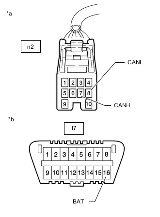
*a Front view of wire harness connector
(to Power Steering ECU Assembly)
*b Front view of DLC3 Disconnect the power steering ECU assembly connector.
-
Measure the resistance according to the value(s) in the table below.
Standard Resistance Tester Connection Condition Specified Condition n2-7 (CANH) - I7-16 (BAT) Cable disconnected from negative (-) auxiliary battery terminal 6 kΩ or higher n2-8 (CANL) - I7-16 (BAT) Cable disconnected from negative (-) auxiliary battery terminal 6 kΩ or higher Result Proceed to OK NG
OK
REPLACE POWER STEERING ECU ASSEMBLY Click here
NG
REPAIR OR REPLACE CAN BRANCH WIRE CONNECTED TO POWER STEERING ECU ASSEMBLY (CANH, CANL)
-
-
CONNECT CONNECTOR
-
Reconnect the No. 2 CAN junction connector.
Result Proceed to NEXT
NEXT
-
-
CHECK FOR SHORT TO B+ IN CAN BUS WIRE (POWER STEERING ECU ASSEMBLY BRANCH WIRE)
-
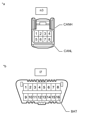
*a Front view of wire harness connector
(to Power Steering ECU Assembly)
*b Front view of DLC3 Disconnect the power steering ECU assembly connector.
-
Measure the resistance according to the value(s) in the table below.
Standard Resistance Tester Connection Condition Specified Condition n3-4 (CANH) - I7-16 (BAT) Cable disconnected from negative (-) auxiliary battery terminal 6 kΩ or higher n3-8 (CANL) - I7-16 (BAT) Cable disconnected from negative (-) auxiliary battery terminal 6 kΩ or higher Result Proceed to OK NG
OK
REPLACE POWER STEERING ECU ASSEMBLY Click here
NG
REPAIR OR REPLACE CAN BRANCH WIRE CONNECTED TO POWER STEERING ECU ASSEMBLY (CANH, CANL)
-
-
CONNECT CONNECTOR
-
Reconnect the No. 3 CAN junction connector.
Result Proceed to NEXT
NEXT
-
-
CHECK FOR SHORT TO B+ IN CAN BUS WIRE (RADIO RECEIVER ASSEMBLY BRANCH WIRE)
-
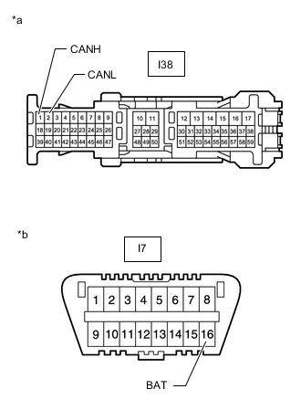
*a Front view of wire harness connector
(to Radio Receiver Assembly)
*b Front view of DLC3 Disconnect the radio receiver assembly connector.
-
Measure the resistance according to the value(s) in the table below.
Standard Resistance Tester Connection Condition Specified Condition I38-1 (CANH) - I7-16 (BAT) Cable disconnected from negative (-) auxiliary battery terminal 6 kΩ or higher I38-2 (CANL) - I7-16 (BAT) Cable disconnected from negative (-) auxiliary battery terminal 6 kΩ or higher Result Proceed to OK NG
OK
REPLACE RADIO RECEIVER ASSEMBLY Click here
NG
REPAIR OR REPLACE CAN BRANCH WIRE CONNECTED TO RADIO RECEIVER ASSEMBLY (CANH, CANL)
-
-
CONNECT CONNECTOR
-
Reconnect the No. 3 CAN junction connector.
Result Proceed to NEXT
NEXT
-
-
CHECK FOR SHORT TO B+ IN CAN BUS WIRE (RADIO RECEIVER ASSEMBLY BRANCH WIRE)
-
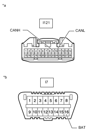
*a Front view of wire harness connector
(to Radio Receiver Assembly)
*b Front view of DLC3 Disconnect the radio receiver assembly connector.
-
Measure the resistance according to the value(s) in the table below.
Standard Resistance Tester Connection Condition Specified Condition I121-9 (CANH) - I7-16 (BAT) Cable disconnected from negative (-) auxiliary battery terminal 6 kΩ or higher I121-10 (CANL) - I7-16 (BAT) Cable disconnected from negative (-) auxiliary battery terminal 6 kΩ or higher Result Proceed to OK NG
OK
REPLACE RADIO RECEIVER ASSEMBLY Click here
NG
REPAIR OR REPLACE CAN BRANCH WIRE CONNECTED TO RADIO RECEIVER ASSEMBLY (CANH, CANL)
-
-
CONNECT CONNECTOR
-
Reconnect the No. 3 CAN junction connector.
Result Proceed to NEXT
NEXT
-
-
CHECK FOR SHORT TO B+ IN CAN BUS WIRE (MAIN BODY ECU BRANCH WIRE)
-
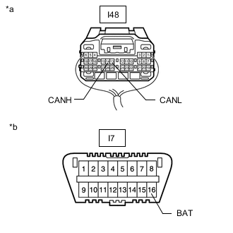
*a Rear view of wire harness connector
(to Main Body ECU [Multiplex Network Body ECU])
*b Front view of DLC3 Disconnect the main body ECU (multiplex network body ECU) connector.
-
Measure the resistance according to the value(s) in the table below.
Standard Resistance Tester Connection Condition Specified Condition I48-14 (CANH) - I7-16 (BAT) Cable disconnected from negative (-) auxiliary battery terminal 6 kΩ or higher I48-13 (CANL) - I7-16 (BAT) Cable disconnected from negative (-) auxiliary battery terminal 6 kΩ or higher Result Proceed to OK NG
OK
REPLACE MAIN BODY ECU (MULTIPLEX NETWORK BODY ECU) Click here
NG
REPAIR OR REPLACE CAN BRANCH WIRE CONNECTED TO MAIN BODY ECU (CANH, CANL)
-
-
CONNECT CONNECTOR
-
Reconnect the No. 3 CAN junction connector.
Result Proceed to NEXT
NEXT
-
-
CHECK FOR SHORT TO B+ IN CAN BUS WIRE (ECM)
-
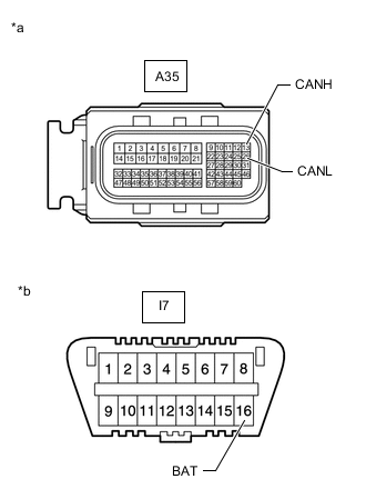
*a Front view of wire harness connector
(to ECM)
*b Front view of DLC3 Disconnect the ECM connector.
-
Measure the resistance according to the value(s) in the table below.
Standard Resistance Tester Connection Condition Specified Condition A35-13 (CANH) - I7-16 (BAT) Cable disconnected from negative (-) auxiliary battery terminal 6 kΩ or higher A35-26 (CANL) - I7-16 (BAT) Cable disconnected from negative (-) auxiliary battery terminal 6 kΩ or higher Result Proceed to OK NG
OK
REPLACE ECM Click here
NG
REPAIR OR REPLACE CAN MAIN WIRE CONNECTED TO ECM (CANH, CANL)
-
-
CONNECT CONNECTOR
-
Reconnect the No. 3 CAN junction connector.
Result Proceed to NEXT
NEXT
-
-
CHECK FOR SHORT TO B+ IN CAN BUS WIRE (SKID CONTROL ECU BRANCH WIRE)
-
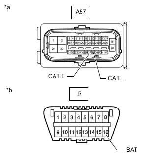
*a Front view of wire harness connector
(to Brake Booster with Master Cylinder Assembly [Skid Control ECU])
*b Front view of DLC3 Disconnect the brake booster with master cylinder assembly (skid control ECU) connector.
-
Measure the resistance according to the value(s) in the table below.
Standard Resistance Tester Connection Condition Specified Condition A57-37 (CA1H) - I7-16 (BAT) Cable disconnected from negative (-) auxiliary battery terminal 6 kΩ or higher A57-38 (CA1L) - I7-16 (BAT) Cable disconnected from negative (-) auxiliary battery terminal 6 kΩ or higher Result Proceed to OK NG
OK
REPLACE BRAKE BOOSTER WITH MASTER CYLINDER ASSEMBLY Click here
NG
REPAIR OR REPLACE CAN BRANCH WIRE CONNECTED TO SKID CONTROL ECU (CA1H, CA1L)
-
-
CONNECT CONNECTOR
-
Reconnect the No. 2 CAN junction connector.
Result Proceed to NEXT
NEXT
-
-
CHECK FOR SHORT TO B+ IN CAN BUS WIRE (STEERING ANGLE SENSOR BRANCH WIRE)
-
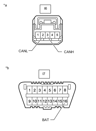
*a Front view of wire harness connector
(to Spiral with Sensor Cable Sub-assembly [Steering Angle Sensor])
*b Front view of DLC3 Disconnect the spiral with sensor cable sub-assembly (steering angle sensor) connector.
-
Measure the resistance according to the value(s) in the table below.
Standard Resistance Tester Connection Condition Specified Condition I6-3 (CANH) - I7-16 (BAT) Cable disconnected from negative (-) auxiliary battery terminal 6 kΩ or higher I6-2 (CANL) - I7-16 (BAT) Cable disconnected from negative (-) auxiliary battery terminal 6 kΩ or higher Result Proceed to OK NG
OK
REPLACE SPIRAL WITH SENSOR CABLE SUB-ASSEMBLY (STEERING ANGLE SENSOR) Click here
NG
REPAIR OR REPLACE CAN BRANCH WIRE CONNECTED TO SPIRAL WITH SENSOR CABLE SUB-ASSEMBLY (CANH, CANL)
-
-
CONNECT CONNECTOR
-
Reconnect the No. 3 CAN junction connector.
Result Proceed to NEXT
NEXT
-
-
CHECK FOR SHORT TO B+ IN CAN BUS WIRE (PARKING BRAKE ECU ASSEMBLY BRANCH WIRE)
-
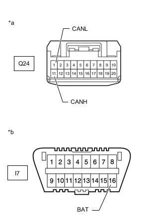
*a Front view of wire harness connector
(to Parking Brake ECU Assembly)
*b Front view of DLC3 Disconnect the parking brake ECU assembly connector.
-
Measure the resistance according to the value(s) in the table below.
Standard Resistance Tester Connection Condition Specified Value Q24-11 (CANH) - I7-16 (BAT) Cable disconnected from negative (-) auxiliary battery terminal 6 kΩ or higher Q24-1 (CANL) - I7-16 (BAT) Cable disconnected from negative (-) auxiliary battery terminal 6 kΩ or higher Result Proceed to OK NG
OK
REPLACE PARKING BRAKE ECU ASSEMBLY Click here
NG
REPAIR OR REPLACE CAN BRANCH WIRE CONNECTED TO PARKING BRAKE ECU ASSEMBLY (CANH, CANL)
-