CAN COMMUNICATION SYSTEM(for LHD) SYSTEM DIAGRAM
-
SYSTEM DIAGRAM
-
Overall CAN Bus Diagram
-
Control system CAN is composed of 5 buses.
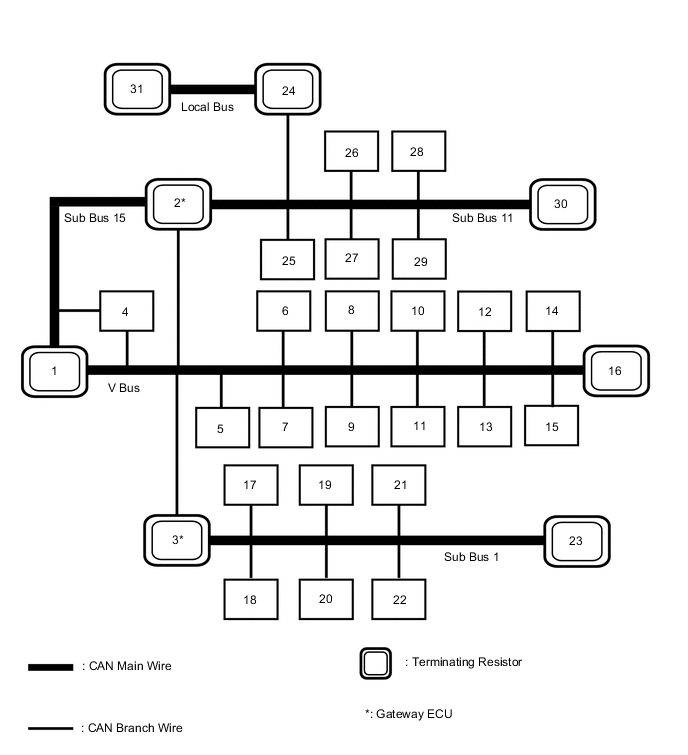
No. ECU/Sensor Name 1 ECM 2 Hybrid vehicle control ECU 3 Main body ECU (multiplex network body ECU) 4 Brake booster with master cylinder assembly (skid control ECU) 5 Parking brake ECU assembly 6 Power steering ECU assembly 7 Air conditioning amplifier assembly 8 Stereo component equalizer assembly*1 9 Certification ECU (smart key ECU assembly) 10 Spiral with sensor cable sub-assembly (steering angle sensor) 11 DLC3 12 Airbag ECU assembly 13 Radio receiver assembly*2 14 Telematics transceiver*12 15 Bus buffer ECU 16 Combination meter assembly 17 Multiplex tilt and telescopic ECU*3 18 Outer mirror control ECU assembly RH*4 19 Outer mirror control ECU assembly LH*4 20 Front power seat switch LH*4 21 Headlight light control ECU sub-assembly LH 22 Multiplex network door ECU*5 23 No. 2 CAN junction terminal 24 Driving support ECU assembly*6 25 Clearance warning ECU assembly*7 26 Parking assist ECU*8 27 Lane departure warning camera*9 28 Blind spot monitor sensor LH*10 29 Absorber control ECU*11 30 No. 1 CAN junction terminal 31 Millimeter wave radar sensor assembly*6 *1: w/ ASC System
*2: w/ Navigation System or Audio and Visual System
*3: for Power Tilt and Power Telescopic Steering Column
*4: w/ Memory
*5: w/ Power Back Door System
*6: w/ Pre-crash Safety System
*7: w/ LEXUS Parking Assist-sensor System
*8: w/ Panoramic View Monitor System
*9: w/ Lane Departure Alert System
*10: w/ Blind Spot Monitor System
*11: w/ Adaptive Variable Suspension System
*12: w/ Emergency Call Switch
Tech Tips
-
The main body ECU (multiplex network body ECU) functions as a gateway between the V bus and sub bus 1.
-
The hybrid vehicle control ECU functions as a gateway between the V bus and sub bus 11.
-
Refer to the following bus wiring diagrams for details.
-
-
-
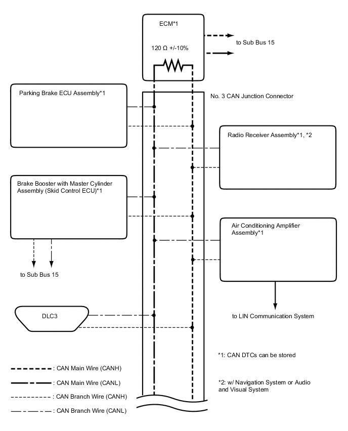
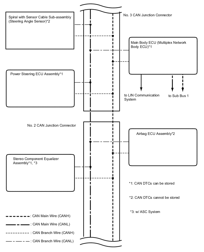
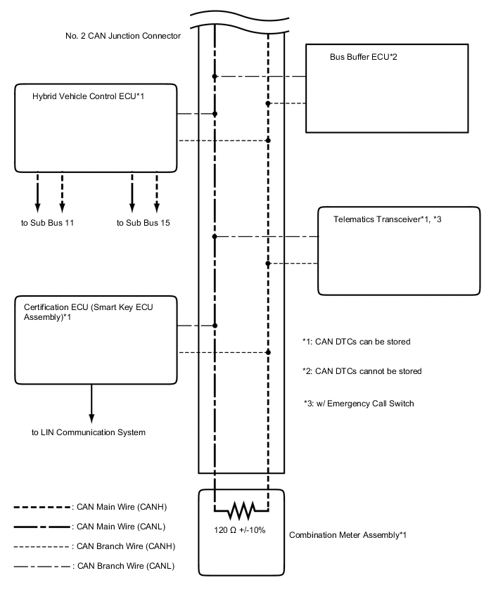
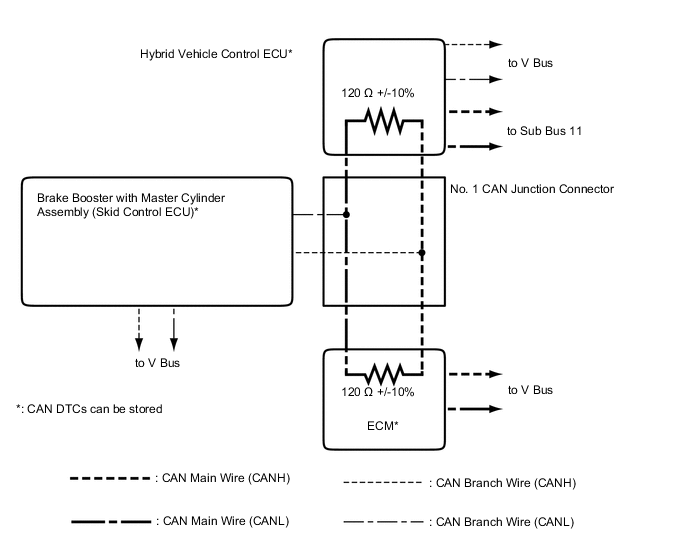
V Bus
Tech Tips
The CAN communication system connects to other networks via ECUs that function as gateways.
-
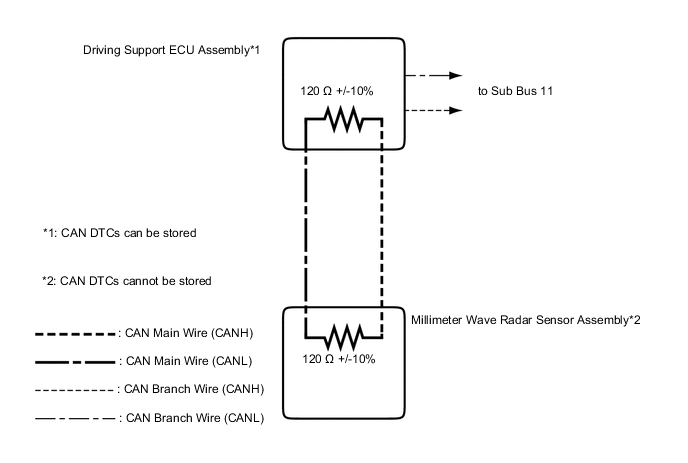
Sub Bus 11
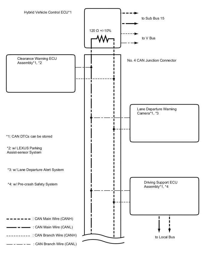
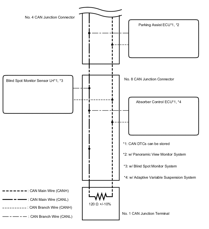
-
Sub Bus 1
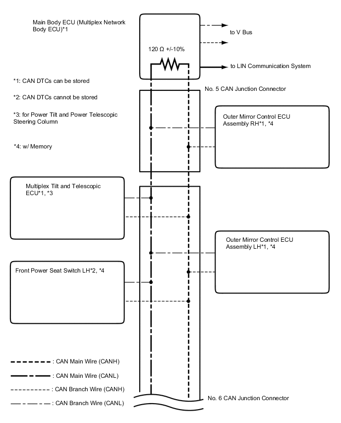
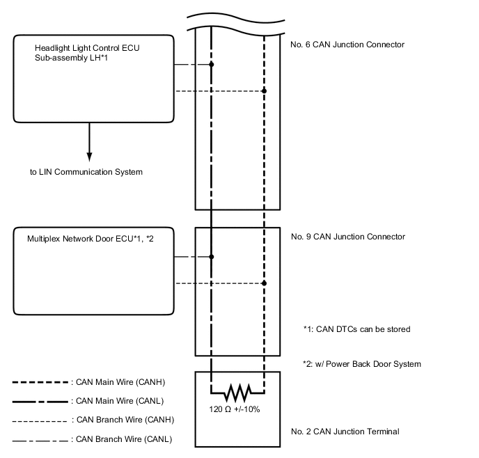
Tech Tips
The CAN communication system connects to other networks via ECUs that function as gateways.
-
Sub Bus 15
-
Local Bus (w/ Pre-crash Safety System)
-