CAN COMMUNICATION SYSTEM Check Bus 2 Lines for Short Circuit
DESCRIPTION
There may be a short circuit between the CAN main bus wire and/or CAN branch wire when the resistance between terminals 18 (CA4H) and 17 (CA4L) of the central gateway ECU (network gateway ECU) is below 54 Ω.
| Symptom | Trouble Area |
|---|---|
| Resistance between terminals 18 (CA4H) and 17 (CA4L) of central gateway ECU (network gateway ECU) is below 54 Ω. |
|
*2: w/ ASC System
WIRING DIAGRAM
-
for LHD:
-
for RHD:
CAUTION / NOTICE / HINT
CAUTION:
When performing the confirmation driving pattern, obey all speed limits and traffic laws.
Note
-
Because the order of diagnosis is important to allow correct diagnosis, make sure to begin troubleshooting using How to Proceed with Troubleshooting when CAN communication system related DTCs are output.
-
Before measuring the resistance of the CAN bus, turn the power switch off and leave the vehicle for 1 minute or more without operating the key or any switches, or opening or closing the doors. After that, disconnect the cable from the negative (-) auxiliary battery terminal and leave the vehicle for 1 minute or more before measuring the resistance.
-
After turning the power switch off, waiting time may be required before disconnecting the cable from the negative (-) auxiliary battery terminal. Therefore, make sure to read the disconnecting the cable from the negative (-) auxiliary battery terminal notices before proceeding with work.
-
Some parts must be initialized and set when replacing or removing and installing parts.
-
After performing repairs, perform the DTC check procedure and confirm that the DTCs are not output again.
DTC check procedure: Turn the power switch on (IG) and wait for 1 minute or more. Then operate the suspected malfunctioning system and drive the vehicle at 60 km/h (37 mph) or more for 5 minutes or more.
-
After the repair, perform the CAN bus check and check that all the ECUs and sensors connected to the CAN communication system are displayed as normal.
-
Before replacing the certification ECU (smart key ECU assembly), refer to Service Bulletin.
-
When replacing the combination meter assembly, always replace it with a new one. If a combination meter assembly which was installed to another vehicle is used, the information stored in it will not match the information from the vehicle and a DTC may be stored.
Tech Tips
-
Operating the power switch, any switches or any doors triggers related ECU and sensor communication with the CAN, which causes resistance variation.
-
Even after DTCs are cleared, if a DTC is stored again after driving the vehicle for a while, the malfunction may be occurring due to vibration of the vehicle. In such a case, wiggling the ECUs or wire harness while performing the inspection below may help determine the cause of the malfunction.
PROCEDURE
-
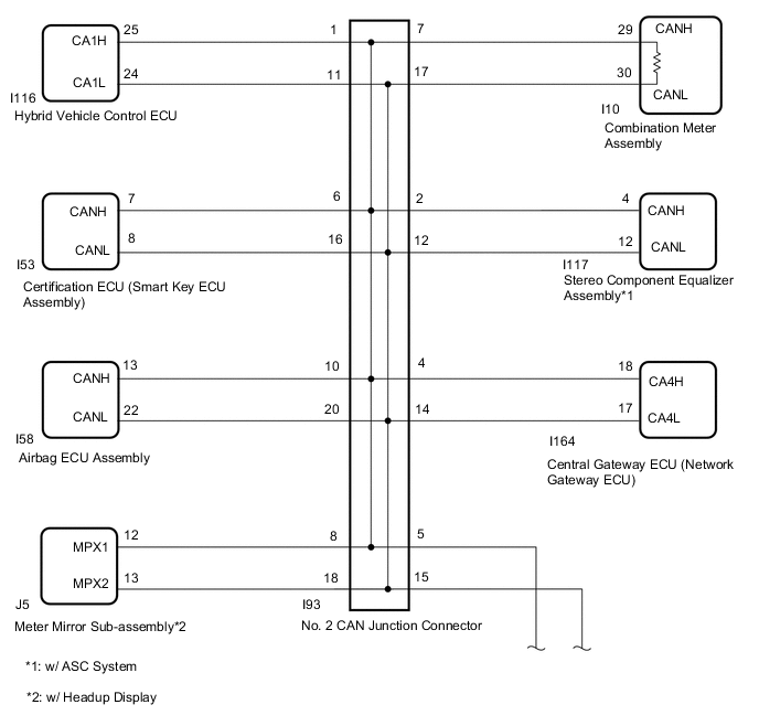
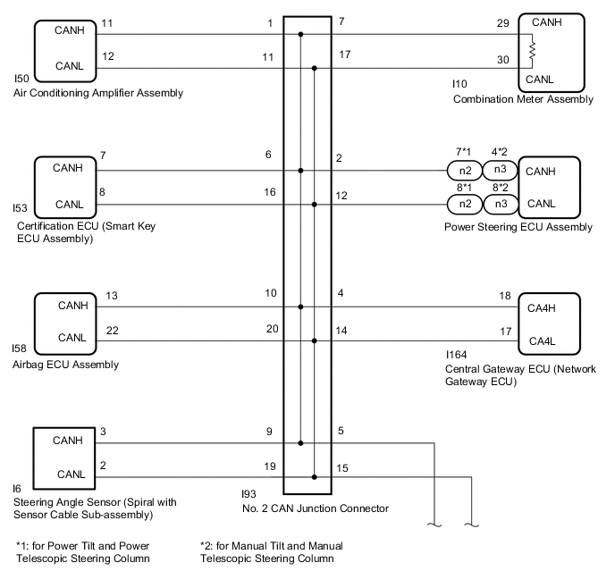
CHECK FOR SHORT IN CAN BUS WIRES (NO. 2 CAN JUNCTION CONNECTOR)
-
Disconnect the cable from the negative (-) auxiliary battery terminal.
-
Disconnect the No. 2 CAN junction connector.
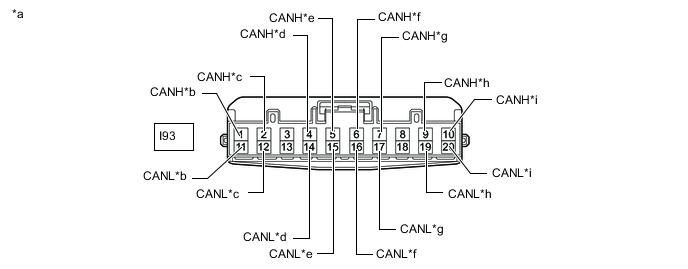
*a Front view of wire harness connector
(to No. 2 CAN Junction Connector)
*b
-
to Hybrid Vehicle Control ECU (for LHD)
-
to Air Conditioning Amplifier Assembly (for RHD)
*c
-
to Stereo Component Equalizer Assembly (for LHD with ASC System)
-
to Power Steering ECU Assembly (for RHD)
*d to Central Gateway ECU (Network Gateway ECU) *e to No. 3 CAN Junction Connector *f to Certification ECU (Smart Key ECU Assembly) *g to Combination Meter Assembly *h
-
to Steering Angle Sensor (Spiral with Sensor Cable Sub-assembly) (for RHD)
-
to Meter Mirror Sub-assembly (for LHD with Headup Display)
*i to Airbag ECU Assembly - - -
-
Measure the resistance according to the value(s) in the table below.
Standard Resistance *1: for LHDTester Connection Condition Specified Condition Connected to I93-1 (CANH) - I93-11 (CANL) Cable disconnected from negative (-) auxiliary battery terminal 200 Ω or higher
-
Hybrid vehicle control ECU*1
-
Air conditioning amplifier assembly*2
I93-2 (CANH) - I93-12 (CANL) Cable disconnected from negative (-) auxiliary battery terminal 200 Ω or higher
-
Stereo component equalizer assembly*3
-
Power steering ECU assembly*2
I93-4 (CANH) - I93-14 (CANL) Cable disconnected from negative (-) auxiliary battery terminal 200 Ω or higher Central gateway ECU (network gateway ECU) I93-5 (CANH) - I93-15 (CANL) Cable disconnected from negative (-) auxiliary battery terminal 108 to 132 Ω No. 3 CAN junction connector I93-6 (CANH) - I93-16 (CANL) Cable disconnected from negative (-) auxiliary battery terminal 200 Ω or higher Certification ECU (smart key ECU assembly) I93-7 (CANH) - I93-17 (CANL) Cable disconnected from negative (-) auxiliary battery terminal 108 to 132 Ω Combination meter assembly I93-9 (CANH) - I93-19 (CANL) Cable disconnected from negative (-) auxiliary battery terminal 200 Ω or higher
-
Steering angle sensor (spiral with sensor cable sub-assembly)*2
-
Meter mirror sub-assembly*4
I93-10 (CANH) - I93-20 (CANL) Cable disconnected from negative (-) auxiliary battery terminal 200 Ω or higher Airbag ECU assembly
*2: for RHD
*3: for LHD with ASC System
*4: for LHD with Headup Display
Result Result Proceed to OK A NG (Central gateway ECU [network gateway ECU] CAN branch wire) B NG (No. 3 CAN junction connector CAN main wire) C NG (Wire to ECU or sensor) D -
A 
REPLACE NO. 2 CAN JUNCTION CONNECTOR
C 
CONNECT CONNECTOR Click here
D
GO TO STEP 8 Click here
B 
-
-
CONNECT CONNECTOR
-
Reconnect the I93 No. 2 CAN junction connector.
Result Proceed to NEXT
NEXT
-
-
CHECK FOR SHORT IN CAN BUS WIRES (CENTRAL GATEWAY ECU [NETWORK GATEWAY ECU] - NO. 2 CAN JUNCTION CONNECTOR)
-
Disconnect the central gateway ECU (network gateway ECU) connector.
-
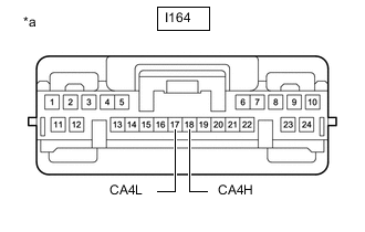
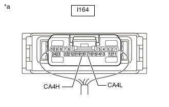
*a Front view of wire harness connector
(to Central Gateway ECU [Network Gateway ECU])
Disconnect the No. 2 CAN junction connector.
-
Measure the resistance according to the value(s) in the table below.
Standard Resistance Tester Connection Condition Specified Condition I164-18 (CA4H) - I164-17 (CA4L) Cable disconnected from negative (-) auxiliary battery terminal 108 to 132 Ω Result Proceed to OK NG
OK
REPLACE CENTRAL GATEWAY ECU (NETWORK GATEWAY ECU) fro LHD: Click here
REPLACE CENTRAL GATEWAY ECU (NETWORK GATEWAY ECU) fro RHD: Click hereNG
REPAIR OR REPLACE CAN BRANCH WIRE OR CONNECTOR (CENTRAL GATEWAY ECU [NETWORK GATEWAY ECU] - NO. 2 CAN JUNCTION CONNECTOR)
-
-
CONNECT CONNECTOR
-
Reconnect the I93 No. 2 CAN junction connector.
Result Proceed to NEXT
NEXT
-
-
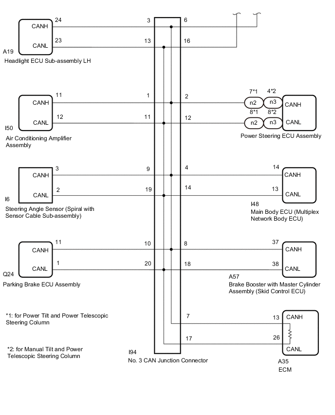
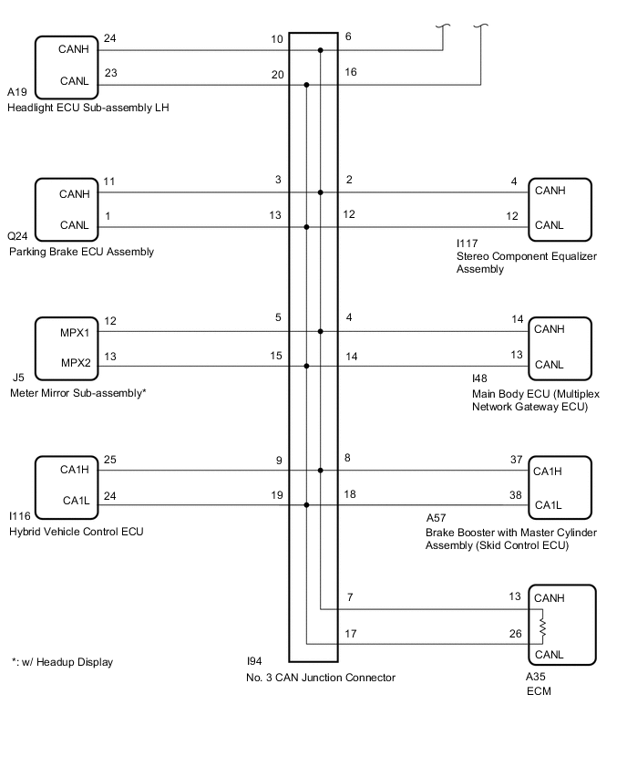
CHECK FOR SHORT IN CAN BUS WIRES (NO. 3 CAN JUNCTION CONNECTOR)
-
Disconnect the No. 3 CAN junction connector.
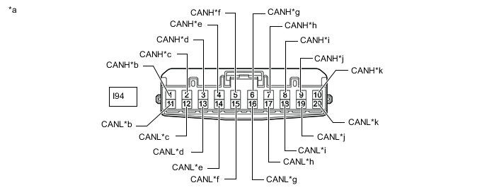
*a Front view of wire harness connector
(to No. 3 CAN Junction Connector)
*b to Air Conditioning Amplifier Assembly (for LHD) *c
-
to Power Steering ECU Assembly (for LHD)
-
to Stereo Component Equalizer Assembly (for RHD with ASC System)
*d
-
to Parking Brake ECU Assembly (for RHD)
-
to Headlight ECU Sub-assembly LH (for LHD)
*e to Main Body ECU (Multiplex Network Gateway ECU) *f to Meter Mirror Sub-assembly (for RHD with Headup Display) *g to No. 2 CAN Junction Connector *h to ECM *i to Brake Booster with Master Cylinder Assembly (Skid Control ECU) *j
-
to Steering Angle Sensor (Spiral with Sensor Cable Sub-assembly) (for LHD)
-
to Hybrid Vehicle Control ECU (for RHD)
*k
-
to Headlight ECU Sub-assembly LH (for RHD)
-
to Parking Brake ECU Assembly (for LHD)
- - -
-
Measure the resistance according to the value(s) in the table below.
Standard Resistance *1: for LHDTester Connection Condition Specified Condition Connected to I94-1 (CANH) - I94-11 (CANL) Cable disconnected from negative (-) auxiliary battery terminal 200 Ω or higher Air conditioning amplifier assembly*1 I94-2 (CANH) - I94-12 (CANL) Cable disconnected from negative (-) auxiliary battery terminal 200 Ω or higher
-
Power steering ECU assembly*1
-
Stereo component equalizer assembly*2
I94-3 (CANH) - I94-13 (CANL) Cable disconnected from negative (-) auxiliary battery terminal 200 Ω or higher
-
Headlight ECU sub-assembly LH*1
-
Parking brake ECU assembly*2
I94-4 (CANH) - I94-14 (CANL) Cable disconnected from negative (-) auxiliary battery terminal 200 Ω or higher Main body ECU (multiplex network gateway ECU) I94-5 (CANH) - I94-15 (CANL) Cable disconnected from negative (-) auxiliary battery terminal 200 Ω or higher Meter mirror sub-assembly*3 I94-6 (CANH) - I94-16 (CANL) Cable disconnected from negative (-) auxiliary battery terminal 108 to 132 Ω No. 2 CAN junction connector I94-7 (CANH) - I94-17 (CANL) Cable disconnected from negative (-) auxiliary battery terminal 108 to 132 Ω ECM I94-8 (CANH) - I94-18 (CANL) Cable disconnected from negative (-) auxiliary battery terminal 200 Ω or higher Brake booster with master cylinder assembly (skid control ECU) I94-9 (CANH) - I94-19 (CANL) Cable disconnected from negative (-) auxiliary battery terminal 200 Ω or higher
-
Steering angle sensor (spiral with sensor cable sub-assembly)*1
-
Hybrid vehicle control ECU*2
I94-10 (CANH) - I94-20 (CANL) Cable disconnected from negative (-) auxiliary battery terminal 200 Ω or higher
-
Parking brake ECU assembly*1
-
Headlight ECU sub-assembly LH*2
*2: for RHD
*3: for RHD with Headup Display
Result Result Proceed to OK A NG (ECM CAN main wire) B NG (No. 2 CAN junction connector CAN main wire) C NG (Wire to ECU or sensor) D -
A
REPLACE NO. 3 CAN JUNCTION CONNECTOR
C
REPAIR OR REPLACE CAN MAIN WIRE OR CONNECTOR (NO. 3 CAN JUNCTION CONNECTOR - NO. 2 CAN JUNCTION CONNECTOR)
D
CHECK FOR SHORT IN CAN BUS WIRES (ECU, SENSOR) Click here
B
-
-
CONNECT CONNECTOR
-
Reconnect the I94 No. 3 CAN junction connector.
Result Proceed to NEXT
NEXT
-
-
CHECK FOR SHORT IN CAN BUS WIRES (ECM - NO. 3 CAN JUNCTION CONNECTOR)
-
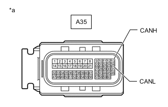
*a Front view of wire harness connector
(to ECM)
Disconnect the ECM connector.
-
Measure the resistance according to the value(s) in the table below.
Standard Resistance Tester Connection Condition Specified Condition A35-13 (CANH) - A35-26 (CANL) Cable disconnected from negative (-) auxiliary battery terminal 108 to 132 Ω Result Proceed to OK NG
OK
REPLACE ECM Click here
NG
REPAIR OR REPLACE CAN MAIN WIRE OR CONNECTOR (ECM - NO. 3 CAN JUNCTION CONNECTOR)
-
-
CHECK FOR SHORT IN CAN BUS WIRES (ECU, SENSOR)
-
Reconnect all wire harness connectors.
-
Disconnect the connector that includes terminals CANH and CANL from the ECU or sensor to which the short circuited branch line is connected.
-
*a Component with harness connected
(Central Gateway ECU [Network Gateway ECU])
Measure the resistance according to the value(s) in the table below.
Standard Resistance Tester Connection Condition Specified Condition I164-18 (CA4H) - I164-17 (CA4L) Cable disconnected from negative (-) auxiliary battery terminal 54 to 69 Ω Tech Tips
If the resistance becomes normal (between 54 and 69 Ω) when the connector is disconnected from the ECU or sensor, there may be a short in the ECU or sensor.
Result Proceed to OK NG
OK
REPLACE ECU OR SENSOR
NG
REPAIR OR REPLACE HARNESS OR CONNECTOR
-