CAN COMMUNICATION SYSTEM Power Steering ECU Communication Stop Mode
DESCRIPTION
| Detection Item | Symptoms | Trouble Area |
|---|---|---|
| Power Steering ECU Communication Stop Mode | Any of the following conditions are met:
|
|
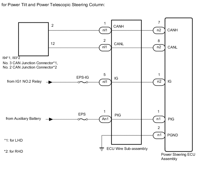
WIRING DIAGRAM

CAUTION / NOTICE / HINT
CAUTION:
When performing the confirmation driving pattern, obey all speed limits and traffic laws.
Note
-
Because the order of diagnosis is important to allow correct diagnosis, make sure to begin troubleshooting using How to Proceed with Troubleshooting when CAN communication system related DTCs are output.
-
Before measuring the resistance of the CAN bus, turn the power switch off and leave the vehicle for 1 minute or more without operating the key, switches or opening or closing the doors. After that, disconnect the cable from the negative (-) auxiliary battery terminal and leave the vehicle for 1 minute or more before measuring the resistance.
-
After turning the power switch off, waiting time may be required before disconnecting the cable from the negative (-) auxiliary battery terminal. Therefore, make sure to read the disconnecting the cable from the negative (-) auxiliary battery terminal notice before proceeding with work.
-
Some parts must be initialized and set when replacing or removing and installing parts.
-
Inspect the fuses for circuits related to this system before performing the following inspection procedure.
-
After performing repairs, perform the DTC check procedure and confirm that the DTCs are not output again.
DTC check procedure: Turn the power switch on (IG) and wait for 1 minute or more. Then operate the suspected malfunctioning system and drive the vehicle at 60 km/h (37 mph) or more for 5 minutes or more.
-
After the repair, perform CAN Bus Check and check that all the ECUs and sensors connected to the CAN communication system are displayed as normal.
Tech Tips
-
Operating the power switch, any switches or any doors triggers related ECU and sensor communication with the CAN, which causes resistance variation.
-
Even after DTCs are cleared, if a DTC is stored again after driving the vehicle for a while, the malfunction may be occurring due to vibration of the vehicle. In such a case, wiggling the ECUs or wire harness while performing the inspection below may help determine the cause of the malfunction.
PROCEDURE
-
CHECK VEHICLE TYPE
-
Check vehicle type.
Result Result Proceed to for Power Tilt and Power Telescopic Steering Column A for Manual Tilt and Manual Telescopic Steering Column B
B 
CHECK FOR OPEN IN CAN BUS WIRE (POWER STEERING ECU ASSEMBLY BRANCH WIRE) Click here
A 
-
-
CHECK FOR OPEN IN CAN BUS WIRE (POWER STEERING ECU ASSEMBLY BRANCH WIRE)
-
Disconnect the cable from the negative (-) auxiliary battery terminal.
-
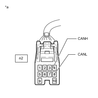
*a Front view of wire harness connector
(to Power Steering ECU Assembly)
Disconnect the power steering ECU assembly connector.
-
Measure the resistance according to the value(s) in the table below.
Standard Resistance Tester Connection Condition Specified Condition n2-7 (CANH) - n2-8 (CANL) Cable disconnected from negative (-) auxiliary battery terminal 54 to 69 Ω Result Proceed to OK NG
NG
CHECK FOR OPEN IN CAN BRANCH WIRE Click here
OK
-
-
CHECK HARNESS AND CONNECTOR (POWER SOURCE CIRCUIT)
-

*a Front view of wire harness connector
(to ECU Wire Sub-assembly)
Reconnect the cable to the negative (-) auxiliary battery terminal.
Note
When disconnecting the cable, some systems need to be initialized after the cable is reconnected.
-
Disconnect the ECU wire sub-assembly connector.
-
Measure the voltage according to the value(s) in the table below.
Standard Voltage Tester Connection Switch Condition Specified Condition An1-1 (PIG) - Body ground Power switch off 9 to 16 V Result Proceed to OK NG
NG 
REPAIR OR REPLACE HARNESS OR CONNECTOR (POWER SOURCE CIRCUIT)
OK
-
-
CHECK HARNESS AND CONNECTOR (POWER SOURCE CIRCUIT)
-
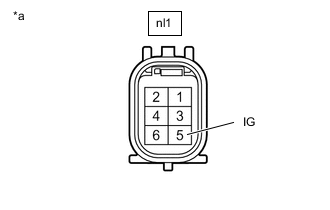
*a Front view of wire harness connector
(to ECU Wire Sub-assembly)
Disconnect the ECU wire sub-assembly connector.
-
Measure the voltage according to the value(s) in the table below.
Standard Voltage Tester Connection Switch Condition Specified Condition nl1-5 (IG) - Body ground Power switch on (IG) 11 to 14 V Power switch off Below 1 V Result Result OK NG
NG
REPAIR OR REPLACE HARNESS OR CONNECTOR (POWER SOURCE CIRCUIT)
OK
-
-
CHECK ECU WIRE SUB-ASSEMBLY
-
Reconnect the ECU wire sub-assembly connectors.
-
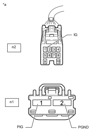
*a Front view of wire harness connector
(to Power Steering ECU Assembly)
Disconnect the power steering ECU assembly connectors.
-
Measure the voltage according to the value(s) in the table below.
Standard Voltage Tester Connection Switch Condition Specified Condition n2-1 (IG) - Body ground Power switch on (IG) 8 to 16 V Power switch off Below 1 V n1-1 (PIG) - Body ground Power switch off 9 to 16 V -
Measure the resistance according to the value(s) in the table below.
Standard Resistance Tester Connection Condition Specified Condition n1-2 (PGND) - Body ground Always Below 1 Ω Result Proceed to OK NG
OK
REPLACE POWER STEERING ECU ASSEMBLY Click here
NG
REPLACE ECU WIRE SUB-ASSEMBLY Click here
-
-
CHECK FOR OPEN IN CAN BRANCH WIRE
-
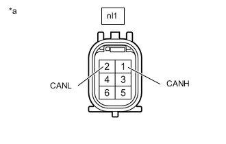
*a Front view of wire harness connector
(to Power Steering ECU Assembly)
Disconnect the ECU wire sub-assembly connector.
-
Measure the resistance according to the value(s) in the table below.
Standard Resistance Tester Connection Condition Specified Condition nl1-1 (CANH) - nl1-2 (CANL) Cable disconnected from negative (-) auxiliary battery terminal 54 to 69 Ω Result Proceed to OK NG
OK
REPLACE ECU WIRE SUB-ASSEMBLY Click here
NG
REPAIR OR REPLACE CAN BRANCH WIRE OR CONNECTOR
-
-
CHECK FOR OPEN IN CAN BUS WIRE (POWER STEERING ECU ASSEMBLY BRANCH WIRE)
-
Disconnect the cable from the negative (-) auxiliary battery terminal.
-
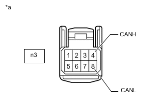
*a Front view of wire harness connector
(to Power Steering ECU Assembly)
Disconnect the power steering ECU assembly connector.
-
Measure the resistance according to the value(s) in the table below.
Standard Resistance Tester Connection Condition Specified Condition n3-4 (CANH) - n3-8 (CANL) Cable disconnected from negative (-) auxiliary battery terminal 54 to 69 Ω Result Proceed to OK NG
NG
CHECK FOR OPEN IN CAN BUS WIRE (POWER STEERING ECU ASSEMBLY BRANCH WIRE) Click here
OK
-
-
CHECK HARNESS AND CONNECTOR (POWER SOURCE CIRCUIT)
-
*a Front view of wire harness connector
(to ECU Wire Sub-assembly)
Reconnect the cable to the negative (-) auxiliary battery terminal.
Note
When disconnecting the cable, some systems need to be initialized after the cable is reconnected.
-
Disconnect the ECU wire sub-assembly connector.
-
Measure the voltage according to the value(s) in the table below.
Standard Voltage Tester Connection Switch Condition Specified Condition An1-1 (PIG) - Body ground Power switch off 9 to 16 V Result Proceed to OK NG
NG
REPAIR OR REPLACE HARNESS OR CONNECTOR (POWER SOURCE CIRCUIT)
OK
-
-
CHECK HARNESS AND CONNECTOR (POWER SOURCE CIRCUIT)
-
*a Front view of wire harness connector
(to ECU Wire Sub-assembly)
Disconnect the ECU wire sub-assembly connector.
-
Measure the voltage according to the value(s) in the table below.
Standard Voltage Tester Connection Switch Condition Specified Condition nl1-5 (IG) - Body ground Power switch on (IG) 11 to 14 V Power switch off Below 1 V Result Proceed to OK NG
NG
REPAIR OR REPLACE HARNESS OR CONNECTOR (POWER SOURCE CIRCUIT)
OK
-
-
CHECK ECU WIRE SUB-ASSEMBLY
-
Reconnect the ECU wire sub-assembly connectors.
-
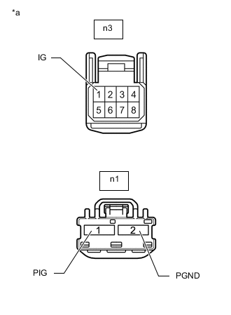
*a Front view of wire harness connector
(to Power Steering ECU Assembly)
Disconnect the power steering ECU assembly connectors.
-
Measure the voltage according to the value(s) in the table below.
Standard Voltage Tester Connection Switch Condition Specified Condition n3-1 (IG) - Body ground Power switch on (IG) 8 to 16 V Power switch off Below 1 V n1-1 (PIG) - Body ground Power switch off 9 to 16 V -
Measure the resistance according to the value(s) in the table below.
Standard Resistance Tester Connection Condition Specified Condition n1-2 (PGND) - Body ground Always Below 1 Ω Result Proceed to OK NG
OK
REPLACE POWER STEERING ECU ASSEMBLY Click here
NG
REPLACE ECU WIRE SUB-ASSEMBLY Click here
-
-
CHECK FOR OPEN IN CAN BUS WIRE (POWER STEERING ECU ASSEMBLY BRANCH WIRE)
-
*a Front view of wire harness connector
(to Power Steering ECU Assembly)
Disconnect the ECU wire sub-assembly connector.
-
Measure the resistance according to the value(s) in the table below.
Standard Resistance Tester Connection Condition Specified Condition nl1-1 (CANH) - nl1-2 (CANL) Cable disconnected from negative (-) auxiliary battery terminal 54 to 69 Ω Result Proceed to OK NG
OK
REPLACE ECU WIRE SUB-ASSEMBLY Click here
NG
REPAIR OR REPLACE CAN BRANCH WIRE OR CONNECTOR
-