CAN COMMUNICATION SYSTEM Hybrid Vehicle Control ECU Communication Stop Mode
DESCRIPTION
| Detection Item | Symptom | Trouble Area |
|---|---|---|
| Hybrid Vehicle Control ECU Communication Stop Mode | Any of the following conditions are met:
|
|
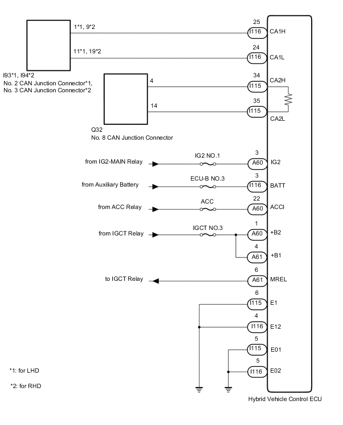
WIRING DIAGRAM
CAUTION / NOTICE / HINT
CAUTION:
When performing the confirmation driving pattern, obey all speed limits and traffic laws.
Note
-
Because the order of diagnosis is important to allow correct diagnosis, make sure to begin troubleshooting using How to Proceed with Troubleshooting when CAN communication system related DTCs are output.
-
Before measuring the resistance of the CAN bus, turn the power switch off and leave the vehicle for 1 minute or more without operating the key, switches or opening or closing the doors. After that, disconnect the cable from the negative (-) auxiliary battery terminal and leave the vehicle for 1 minute or more before measuring the resistance.
-
After turning the power switch off, waiting time may be required before disconnecting the cable from the negative (-) auxiliary battery terminal. Therefore, make sure to read the disconnecting the cable from the negative (-) auxiliary battery terminal notice before proceeding with work.
-
Some parts must be initialized and set when replacing or removing and installing parts.
-
Inspect the fuses for circuits related to this system before performing the following inspection procedure.
-
After performing repairs, perform the DTC check procedure and confirm that the DTCs are not output again.
DTC check procedure: Turn the power switch on (IG) and wait for 1 minute or more. Then operate the suspected malfunctioning system and drive the vehicle at 60 km/h (37 mph) or more for 5 minutes or more.
-
After the repair, perform CAN Bus Check and check that all the ECUs and sensors connected to the CAN communication system are displayed as normal.
Tech Tips
-
Operating the power switch, any other switches or a door triggers related ECU and sensor communication on the CAN. This communication will cause the resistance value to change.
-
Even after DTCs are cleared, if a DTC is stored again after driving the vehicle for a while, the malfunction may be occurring due to vibration of the vehicle. In such a case, wiggling the ECUs or wire harness while performing the inspection below may help determine the cause of the malfunction.
PROCEDURE
-
CHECK FOR OPEN IN CAN BUS WIRE (HYBRID VEHICLE CONTROL ECU MAIN WIRE AND BRANCH WIRE)
-
Disconnect the cable from the negative (-) auxiliary battery terminal.
-
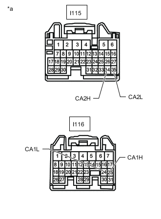
*a Front view of wire harness connector
(to Hybrid Vehicle Control ECU)
Disconnect the hybrid vehicle control ECU connectors.
-
Measure the resistance according to the value(s) in the table below.
Standard Resistance Bus 2 Branch Wire Tester Connection Condition Specified Condition I115-34 (CA2H) - I115-35 (CA2L) Cable disconnected from negative (-) auxiliary battery terminal 54 to 69 Ω Bus 5 Main Wire Tester Connection Condition Specified Condition I116-25 (CA1H) - I116-24 (CA1L) Cable disconnected from negative (-) auxiliary battery terminal 108 to 132 Ω Result Result Proceed to OK A NG (Bus 2 branch wire) B NG (Bus 5 main wire) C
B 
REPAIR OR REPLACE CAN BRANCH WIRE OR CONNECTOR
C
REPAIR OR REPLACE CAN MAIN WIRE OR CONNECTOR
A 
-
-
CHECK HARNESS AND CONNECTOR (POWER SOURCE CIRSUIT)
-
Disconnect the hybrid vehicle control ECU connectors.
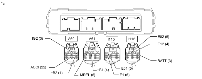
*a Rear view of wire harness connector
(to Hybrid Vehicle Control ECU)
- - -
Measure the resistance according to the value(s) in the table below.
Standard Resistance Tester Connection Condition Specified Condition I115-6 (E1) - Body ground Cable disconnected from negative (-) auxiliary battery terminal Below 1 Ω I115-5 (E01) - Body ground Cable disconnected from negative (-) auxiliary battery terminal Below 1 Ω I116-4 (E12) - Body ground Cable disconnected from negative (-) auxiliary battery terminal Below 1 Ω I116-5 (E02) - Body ground Cable disconnected from negative (-) auxiliary battery terminal Below 1 Ω -
Reconnect the cable to the negative (-) auxiliary battery terminal.
Note
When disconnecting the cable, some systems need to be initialized after the cable is reconnected.
-
Measure the voltage according to the value(s) in the table below.
Standard Voltage Tester Connection Condition Specified Condition I116-3 (BATT) - Body ground Power switch off 11 to 14 V A60-1 (+B2) - Body ground Auxiliary battery voltage applied to terminal A61-6 (MREL) 11 to 14 V A61-4 (+B1) - Body ground Auxiliary battery voltage applied to terminal A61-6 (MREL) 11 to 14 V A60-3 (IG2) - Body ground Power switch on (IG) 11 to 14 V Power switch off Below 1 V A60-22 (ACCI) - Body ground Power switch on (ACC) 11 to 14 V Power switch off Below 1 V Result Proceed to OK NG
OK
REPLACE HYBRID VEHICLE CONTROL ECU Click here
NG
REPAIR OR REPLACE HARNESS OR CONNECTOR (POWER SOURCE CIRSUIT)
-