CAN COMMUNICATION SYSTEM Bus Buffer ECU Communication Stop Mode
DESCRIPTION
| Detection Item | Symptom | Trouble Area |
|---|---|---|
| Bus Buffer ECU Communication Stop Mode | Any condition is met:
|
|
WIRING DIAGRAM
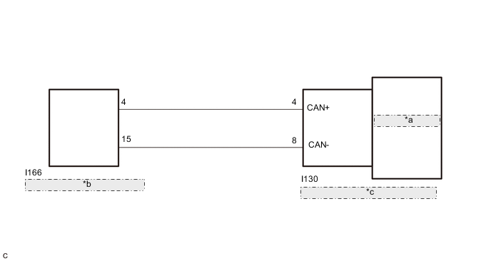
| *a | Dealer-installed Option |
| *b | No. 10 CAN Junction Connector |
| *c | Option Connector (Bus Buffer ECU) |
CAUTION / NOTICE / HINT
CAUTION:
When performing the confirmation driving pattern, obey all speed limits and traffic laws.
Note
-
Because the order of diagnosis is important to allow correct diagnosis, make sure to begin troubleshooting using How to Proceed with Troubleshooting when CAN communication system related DTCs are output.
-
Before measuring the resistance of the CAN bus, turn the power switch off and leave the vehicle for 1 minute or more without operating the key or any switches, or opening or closing the doors. After that, disconnect the cable from the negative (-) auxiliary battery terminal and leave the vehicle for 1 minute or more before measuring the resistance.
-
After turning the power switch off, waiting time may be required before disconnecting the cable from the negative (-) auxiliary battery terminal. Therefore, make sure to read the disconnecting the cable from the negative (-) auxiliary battery terminal notices before proceeding with work.
-
Some parts must be initialized and set when replacing or removing and installing parts.
-
After performing repairs, perform the DTC check procedure and confirm that the DTCs are not output again.
DTC check procedure: Turn the power switch on (IG) and wait for 1 minute or more. Then operate the suspected malfunctioning system and drive the vehicle at 60 km/h (37 mph) or more for 5 minutes or more.
-
After the repair, perform the CAN bus check and check that all the ECUs and sensors connected to the CAN communication system are displayed as normal.
Tech Tips
-
Operating the power switch, any switches or any doors triggers related ECU and sensor communication with the CAN, which causes resistance variation.
-
Even after DTCs are cleared, if a DTC is stored again after driving the vehicle for a while, the malfunction may be occurring due to vibration of the vehicle. In such a case, wiggling the ECUs or wire harness while performing the inspection below may help determine the cause of the malfunction.
PROCEDURE
-
CHECK OPTIONS
-
Check whether dealer installed options that support CAN communication are installed.
Result Result Proceed to Installed A Not installed B
B 
CHECK FOR DTC Click here
A 
-
-
CHECK FOR OPEN IN CAN BUS WIRE (OPTION CONNECTOR [BUS BUFFER ECU] BRANCH WIRE)
-
Disconnect the cable from the negative (-) auxiliary battery terminal.
-
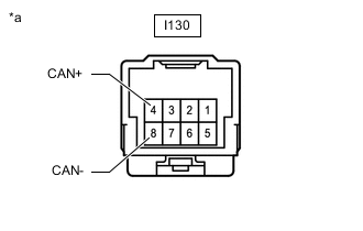
*a Front view of wire harness connector
(to Option Connector [Bus Buffer ECU])
Disconnect the option connector (bus buffer ECU).*
*: When a dealer-installed option is installed
-
Measure the resistance according to the value(s) in the table below.
Standard Resistance Tester Connection Condition Specified Condition I130-4 (CAN+) - I130-8 (CAN-) Cable disconnected from negative (-) auxiliary battery terminal 54 to 69 Ω Result Proceed to OK NG
OK 
CHECK DEALER-INSTALLED OPTION
NG
REPAIR OR REPLACE CAN BRANCH WIRE OR CONNECTOR
-
-
CHECK FOR DTC
-
Connect the GTS to the DLC3.
-
Turn the power switch on (IG).
*: When a dealer-installed option is installed
-
Turn the GTS on.
-
Enter the following menus: Body Electrical / Central Gateway / Utility / Initialization.
Body Electrical > Central Gateway > UtilityTester Display Initialization -
Enter the following menus: Body Electrical / Main Body / Utility / Initialization.
Body Electrical > Main Body > UtilityTester Display Initialization -
Enter the following menus: Body Electrical / Main Body / Clear DTCs.
Body Electrical > Main Body > Clear DTCs -
Enter the following menus: Body Electrical / Main Body / Clear DTCs.
Body Electrical > Main Body > Trouble CodesResult Result Proceed to DTC U1117 is not output from main body ECU (multiplex network body ECU) A DTC U1117 is output from main body ECU (multiplex network body ECU) B
A
END
B
REPLACE MAIN BODY ECU (MULTIPLEX NETWORK BODY ECU) fro LHD: Click here
REPLACE MAIN BODY ECU (MULTIPLEX NETWORK BODY ECU) fro RHD: Click here -