MAIN BODY ECU(for RHD) REMOVAL
PROCEDURE
-
REMOVE NO. 3 DECK BOARD SUB-ASSEMBLY (w/ Spare Tire)
-
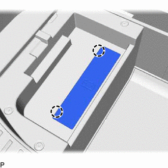
REMOVE REAR DECK FLOOR BOX (w/ Spare Tire)
-
REMOVE DECK FLOOR BOX LH (w/ Spare Tire)
-
PRECAUTION
Note
After turning the power switch off, waiting time may be required before disconnecting the cable from the auxiliary battery negative (-) terminal. Therefore, make sure to read the disconnecting the cable from the auxiliary battery negative (-) terminal notice before proceeding with work.
-
DISCONNECT CABLE FROM NEGATIVE AUXILIARY BATTERY TERMINAL
Note
When disconnecting the cable, some systems need to be initialized after the cable is reconnected.
-
w/o Spare tire:
Detach the 2 claws and remove the battery service cover.
-
Loosen the nut and disconnect the auxiliary battery negative (-) terminal.
-
-
REMOVE GLOVE COMPARTMENT DOOR ASSEMBLY
-
REMOVE NO. 2 INSTRUMENT PANEL UNDER COVER SUB-ASSEMBLY
-
REMOVE HYBRID VEHICLE CONTROL ECU
-
REMOVE INSTRUMENT PANEL JUNCTION BLOCK ASSEMBLY
-
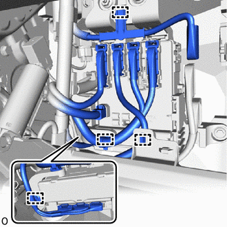
Detach the 4 wire harness clamps.
-
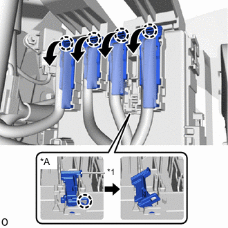
*A w/ Connector Stopper *1 Connector Stopper w/o Connector Stopper:
-
Release the connector lock lever and disconnect the connector.
Tech Tips
Use the same procedure to disconnect the remaining 3 connectors.
-
-
w/ Connector Stopper:
-
Detach the claw and release the connector stopper.
-
Release the connector lock lever and disconnect the connector.
Tech Tips
Use the same procedure to disconnect the remaining 3 connectors.
-
-
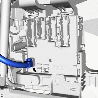
Disconnect the connector from the lower side of the instrument panel junction block assembly.
-
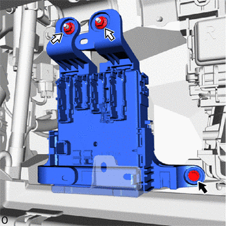
Remove the bolt, 2 nuts and instrument panel junction block assembly.
-
Disconnect the 3 connectors from the multiplex network body ECU (main body ECU).
-
-
REMOVE MULTIPLEX NETWORK BODY ECU (MAIN BODY ECU)
Note
-
If the multiplex network body ECU (main body ECU) is replaced, replace it with a new one.
-
If the multiplex network body ECU (main body ECU) is replaced, refer to the Service Bulletin.
-
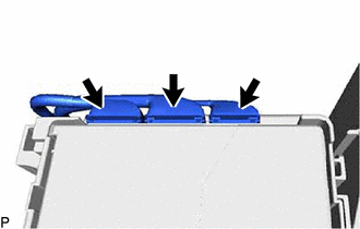
*1 Claw of Junction Block 
Protective Tape Press the claw of the junction block as shown in the illustration to release the lock.
-
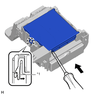
With the junction block lock released, insert a screwdriver with its tip wrapped with protective tape horizontally between the multiplex network body ECU (main body ECU) and junction block.
Note
Use a screwdriver with a diameter of between 5.0 mm (0.197 in.) and 6.3 mm (0.248 in.) and a length of approximately 90 mm (3.54 in.).
-
Protective Tape Using the screwdriver, carefully raise the multiplex network body ECU (main body ECU) up to the position where the connector becomes disengaged.
Note
-
Do not insert the screwdriver opening between the junction block and the connector of the multiplex network body ECU (main body ECU).
-
Do not twist the screwdriver to raise the multiplex network body ECU (main body ECU).
-
-
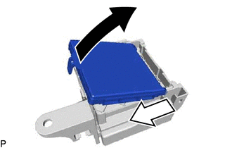

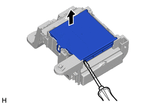
Raise 
Slide Out Raise the multiplex network body ECU (main body ECU) as shown by the black arrow, and then slide it out as shown by the white arrow in the illustration.
Note
Do not touch the ECU connector.
-