PANORAMIC VIEW MONITOR SYSTEM, Diagnostic DTC:C1684
| DTC Code | DTC Name |
|---|---|
| C1684 | Side Camera Current Malfunction |
DESCRIPTION
This DTC is stored if the parking assist ECU judges as a result of its self check that a synchronization problem is occurring in the image signal sent from the passenger side television camera assembly to the parking assist ECU.
| DTC No. | Detection Item | DTC Detection Condition | Trouble Area |
|---|---|---|---|
| C1684 | Side Camera Current Malfunction | Side camera current malfunction |
|
WIRING DIAGRAM
-
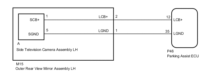
for LHD
-
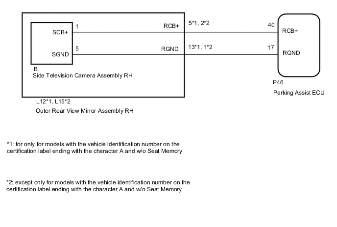
for RHD
CAUTION / NOTICE / HINT
Note
-
When "!" mark is displayed on the multi-display assembly after the cable is disconnected from the negative (-) auxiliary battery terminal, correct the steering angle neutral point.
-
Depending on the parts that are replaced or operations that are performed during vehicle inspection or maintenance, calibration of other systems as well as the panoramic view monitor system may be needed.
PROCEDURE
-
CHECK FOR DTC
-
Clear the DTCs.
Chassis > Panoramic View Monitor > Clear DTCs -
Check for DTCs.
Chassis > Panoramic View Monitor > Trouble CodesOK DTC C1684 is not output. Result Result Proceed to OK A NG (for LHD) B NG (for RHD) C
A 
USE SIMULATION METHOD TO CHECK Click here
C 
CHECK HARNESS AND CONNECTOR (PARKING ASSIST ECU - OUTER REAR VIEW MIRROR ASSEMBLY LH) Click here
B 
-
-
CHECK HARNESS AND CONNECTOR (PARKING ASSIST ECU - OUTER REAR VIEW MIRROR ASSEMBLY RH)
-
Disconnect the P46 parking assist ECU connector.
-
Disconnect the L12*1 or L15*2 outer rear view mirror assembly RH connector.
-
*1: for only for models with the vehicle identification number on the certification label ending with the character A and w/o Seat Memory
-
*2: except only for models with the vehicle identification number on the certification label ending with the character A and w/o Seat Memory
-
-
Measure the resistance according to the value(s) in the table below.
Standard Resistance for only for models with the vehicle identification number on the certification label ending with the character A and w/o Seat Memory Tester Connection Condition Specified Condition P46-40 (RCB+) - L12-5 (RCB+) Always Below 1 Ω P46-17 (RGND) - L12-13 (RGND) Always Below 1 Ω P46-40 (RCB+) or L12-5 (RCB+) - Body ground Always 10 kΩ or higher P46-17 (RGND) or L12-13 (RGND) - Body ground Always 10 kΩ or higher except only for models with the vehicle identification number on the certification label ending with the character A and w/o Seat Memory Tester Connection Condition Specified Condition P46-40 (RCB+) - L15-2 (RCB+) Always Below 1 Ω P46-17 (RGND) - L15-1 (RGND) Always Below 1 Ω P46-40 (RCB+) or L15-2 (RCB+) - Body ground Always 10 kΩ or higher P46-17 (RGND) or L15-1 (RGND) - Body ground Always 10 kΩ or higher Result Proceed to OK NG
NG
REPAIR OR REPLACE HARNESS OR CONNECTOR
OK
-
-
CHECK PARKING ASSIST ECU
-
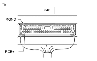
*a Component with harness connected
(Parking Assist ECU)
Disconnect the outer rear view mirror assembly RH connector.
-
Measure the resistance according to the value(s) in the table below.
Standard Resistance Tester Connection Condition Specified Condition P46-17 (RGND) - Body ground Always Below 1 Ω -
Measure the voltage according to the value(s) in the table below.
Standard Voltage Tester Connection Switch Condition Specified Condition P46-40 (RCB+) - P46-17 (RGND) Power switch on (IG) 5.5 to 7.05 V P46-40 (RCB+) - P46-17 (RGND) Power switch off Below 1 V Result Proceed to OK NG
NG
REPLACE PARKING ASSIST ECU Click here
OK
-
-
INSPECT OUTER REAR VIEW MIRROR ASSEMBLY RH
-
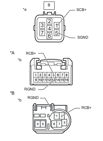
*A for only for models with the vehicle identification number on the certification label ending with the character A and w/o Seat Memory *B except only for models with the vehicle identification number on the certification label ending with the character A and w/o Seat Memory *a Component without harness connected
(to Side Television Camera Assembly RH)
*b Component without harness connected
(to Outer Rear View Mirror Assembly RH)
Disconnect the outer rear view mirror assembly RH connector.
-
Disconnect the side television camera assembly RH connector.
-
Measure the resistance according to the value(s) in the table below.
Standard Resistance for only for models with the vehicle identification number on the certification label ending with the character A and w/o Seat Memory Tester Connection Condition Specified Condition B-1 (SCB+) - 5 (RCB+) Always Below 1 Ω B-5 (SGND) - 13 (RGND) Always Below 1 Ω B-1 (SCB+) or 5 (RCB+) - Body ground Always 10 kΩ or higher B-5 (SGND) or 13 (RGND) - Body ground Always 10 kΩ or higher except only for models with the vehicle identification number on the certification label ending with the character A and w/o Seat Memory Tester Connection Condition Specified Condition B-1 (SCB+) - 2 (RCB+) Always Below 1 Ω B-5 (SGND) - 1 (RGND) Always Below 1 Ω B-1 (SCB+) or 2 (RCB+) - Body ground Always 10 kΩ or higher B-5 (SGND) or 1 (RGND) - Body ground Always 10 kΩ or higher Result Proceed to OK NG
NG
REPLACE OUTER REAR VIEW MIRROR ASSEMBLY RH Click here
OK
-
-
REPLACE SIDE TELEVISION CAMERA ASSEMBLY RH
-
Replace the side television camera assembly RH with a new or normally functioning one.
Result Proceed to NEXT
NEXT
-
-
CHECK FOR DTC
-
Clear the DTCs.
Chassis > Panoramic View Monitor > Clear DTCs -
Check for DTCs.
Chassis > Panoramic View Monitor > Trouble CodesOK DTC C1684 is not output. Result Proceed to OK NG
OK
END (SIDE TELEVISION CAMERA ASSEMBLY RH IS DEFECTIVE)
NG
REPLACE PARKING ASSIST ECU Click here
-
-
CHECK HARNESS AND CONNECTOR (PARKING ASSIST ECU - OUTER REAR VIEW MIRROR ASSEMBLY LH)
-
Disconnect the P46 parking assist ECU connector.
-
Disconnect the M15 outer rear view mirror assembly LH connector.
-
Measure the resistance according to the value(s) in the table below.
Standard Resistance Tester Connection Condition Specified Condition P46-12 (LCB+) - M15-2 (LCB+) Always Below 1 Ω P46-35 (LGND) - M15-1 (LGND) Always Below 1 Ω P46-12 (LCB+) or M15-2 (LCB+) - Body ground Always 10 kΩ or higher P46-35 (LGND) or M15-1 (LGND) - Body ground Always 10 kΩ or higher Result Proceed to OK NG
NG
REPAIR OR REPLACE HARNESS OR CONNECTOR
OK
-
-
CHECK PARKING ASSIST ECU
-
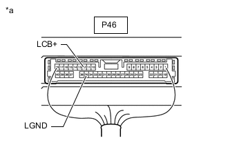
*a Component with harness connected
(Parking Assist ECU)
Disconnect the outer rear view mirror assembly LH connector.
-
Measure the resistance according to the value(s) in the table below.
Standard Resistance Tester Connection Condition Specified Condition P46-35 (LGND) - Body ground Always Below 1 Ω -
Measure the voltage according to the value(s) in the table below.
Standard Voltage Tester Connection Switch Condition Specified Condition P46-12 (LCB+) - P46-35 (LGND) Power switch on (IG) 5.5 to 7.05 V P46-12 (LCB+) - P46-35 (LGND) Power switch off Below 1 V Result Proceed to OK NG
NG
REPLACE PARKING ASSIST ECU Click here
OK
-
-
INSPECT OUTER REAR VIEW MIRROR ASSEMBLY LH
-
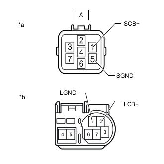
*a Component without harness connected
(to Side Television Camera Assembly LH)
*b Component without harness connected
(to Outer Rear View Mirror Assembly LH)
Disconnect the outer rear view mirror assembly LH connector.
-
Disconnect the side television camera assembly LH connector.
-
Measure the resistance according to the value(s) in the table below.
Standard Resistance Tester Connection Condition Specified Condition A-1 (SCB+) - 2 (LCB+) Always Below 1 Ω A-5 (SGND) - 1 (LGND) Always Below 1 Ω A-1 (SCB+) or 2 (LCB+) - Body ground Always 10 kΩ or higher A-5 (SGND) or 1 (LGND) - Body ground Always 10 kΩ or higher Result Proceed to OK NG
NG
REPLACE OUTER REAR VIEW MIRROR ASSEMBLY LH Click here
OK
-
-
CHECK SIDE TELEVISION CAMERA ASSEMBLY LH
-
Replace the side television camera assembly LH with a new or normally functioning one.
Result Proceed to NEXT
NEXT
-
-
CHECK FOR DTC
-
Clear the DTCs.
Chassis > Panoramic View Monitor > Clear DTCs -
Check for DTCs.
Chassis > Panoramic View Monitor > Trouble CodesOK DTC C1684 is not output. Result Proceed to OK NG
OK
END (SIDE TELEVISION CAMERA ASSEMBLY LH IS DEFECTIVE)
NG
REPLACE PARKING ASSIST ECU Click here
-