LEXUS PARKING ASSIST-SENSOR SYSTEM Clearance Sonar Main Switch Circuit
DESCRIPTION
The combination switch assembly (clearance sonar main switch) is installed at the base of the driver side of the lower instrument panel finish panel sub-assembly.
When the combination switch assembly (clearance sonar main switch) is turned on, an on signal is sent to the clearance warning ECU assembly. The LEXUS parking assist-sensor system operates according to this signal.
WIRING DIAGRAM
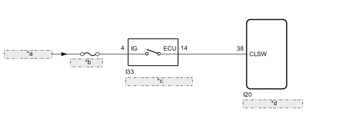
| *a | from IG1 NO.2 Relay |
| *b | ECU-IG NO.2 |
| *c | Combination Switch Assembly (Clearance Sonar Main Switch) |
| *d | Clearance Warning ECU Assembly |
CAUTION / NOTICE / HINT
Note
Inspect the fuses for circuits related to this system before performing the following procedure.
PROCEDURE
-
READ VALUE USING GTS
-
Connect the GTS to the DLC3.
-
Turn the power switch on (IG).
-
Turn the GTS on.
-
Enter the following menus: Body Electrical / Clearance Sonar / Data List.
-
According to the display on the GTS, read the Data List.
Body Electrical > Clearance Sonar > Data ListTester Display Measurement Item Range Normal Condition Diagnostic Note Main Switch Combination switch assembly (clearance sonar main switch) OFF or ON OFF: Combination switch assembly (clearance sonar main switch) off
ON:Combination switch assembly (clearance sonar main switch) on
-
Body Electrical > Clearance Sonar > Data ListTester Display Main Switch Result Result Proceed to The display does not change as shown above when the combination switch assembly (clearance sonar main switch) is operated. A The display changes as shown above when the combination switch assembly (clearance sonar main switch) is operated. B
B 
REPLACE CLEARANCE WARNING ECU ASSEMBLY for LHD REPLACE CLEARANCE WARNING ECU ASSEMBLY Click here
REPLACE CLEARANCE WARNING ECU ASSEMBLY for RHD REPLACE CLEARANCE WARNING ECU ASSEMBLY Click hereA 
-
-
INSPECT COMBINATION SWITCH ASSEMBLY (CLEARANCE SONAR MAIN SWITCH)
-
Remove the combination switch assembly (clearance sonar main switch).
-
Inspect the combination switch assembly (clearance sonar main switch).
Result Proceed to OK NG
NG
REPLACE COMBINATION SWITCH ASSEMBLY (CLEARANCE SONAR MAIN SWITCH) Click here
OK
-
-
CHECK HARNESS AND CONNECTOR (COMBINATION SWITCH ASSEMBLY [CLEARANCE SONAR MAIN SWITCH] - BATTERY)
-
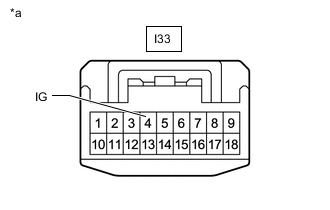
*a Front view of wire harness connector
(to Combination Switch Assembly [Clearance Sonar Main Switch])
Measure the voltage according to the value(s) in the table below.
Standard Voltage Tester Connection Switch Condition Specified Condition I33-4 (IG) - Body ground Power switch on (IG) 11 to 14 V I33-4 (IG) - Body ground Power switch off Below 1 V Result Proceed to OK NG
NG
REPAIR OR REPLACE HARNESS OR CONNECTOR
OK
-
-
CHECK HARNESS AND CONNECTOR (CLEARANCE WARNING ECU ASSEMBLY - COMBINATION SWITCH ASSEMBLY [CLEARANCE SONAR MAIN SWITCH])
-
Disconnect the I20 clearance warning ECU assembly connector.
-
Disconnect the I33 combination switch assembly (clearance sonar main switch) connector.
-
Measure the resistance according to the value(s) in the table below.
Standard Resistance Tester Connection Condition Specified Condition I20-38 (CLSW) -I33-14 (ECU) Always Below 1 Ω I20-38 (CLSW) or I33-14 (ECU) - Body ground Always 10 kΩ or higher Result Proceed to OK NG
OK
REPLACE CLEARANCE WARNING ECU ASSEMBLY for LHD REPLACE CLEARANCE WARNING ECU ASSEMBLY Click here
REPLACE CLEARANCE WARNING ECU ASSEMBLY for RHD REPLACE CLEARANCE WARNING ECU ASSEMBLY Click hereNG
REPAIR OR REPLACE HARNESS OR CONNECTOR
-