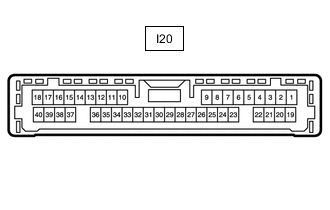
LEXUS PARKING ASSIST-SENSOR SYSTEM TERMINALS OF ECU
-
CLEARANCE WARNING ECU ASSEMBLY
-
Disconnect the clearance warning ECU assembly connector.
-
Measure the voltage and resistance on the wire harness side connector according to the value(s) in the table below.
Terminal No. (Symbol) Wiring Color Terminal Description Condition Specified Condition I20-12 (IG) - I20-27 (E) BE - W-B IG power source signal Power switch off Below 1 V Power switch on (IG) 11 to 14 V I20-27 (E) - Body ground W-B - Body ground Ground Always Below 1 Ω I20-38 (CLSW) - I20-27 (E) LG - W-B Combination switch assembly (clearance sonar main switch) power source signal
-
Power switch on (IG)
-
Combination switch assembly (clearance sonar main switch) off
Below 1 V
-
Power switch on (IG)
-
Combination switch assembly (clearance sonar main switch) on
11 to 14 V -
-
Reconnect the clearance warning ECU assembly connector.
-
Measure the voltage and check for pulses according to the value(s) in the table below.
Terminal No. (Symbol) Wiring Color Terminal Description Condition Specified Condition I20-1 (S1) - I20-2 (E1) B - L Sensor communication signal (Rear corner sensor RH)
-
Power switch on (IG)
-
Combination switch assembly (clearance sonar main switch) on
-
Shift lever in R
Pulse generation
(See waveform 1)
I20-2 (E1) - I20-27 (E) L - W-B Ground for sensor (Rear corner sensor RH) Always Below 1 V I20-3 (S2) - I20-4 (E2) R - L Sensor communication signal (Rear corner sensor LH)
-
Power switch on (IG)
-
Combination switch assembly (clearance sonar main switch) on
-
Shift lever in R
Pulse generation
(See waveform 1)
I20-4 (E2) - I20-27 (E) L - W-B Ground for sensor (Rear corner sensor LH) Always Below 1 V I20-6 (S3) - I20-7 (E3) B - W Sensor communication signal (Rear center sensor RH)
-
Power switch on (IG)
-
Combination switch assembly (clearance sonar main switch) on
-
Shift lever in R
Pulse generation
(See waveform 1)
I20-7 (E3) - I20-27 (E) W - W-B Ground for sensor (Rear center sensor RH) Always Below 1 V I20-8 (S4) - I20-9 (E4) LG - L Sensor communication signal (Rear center sensor LH)
-
Power switch on (IG)
-
Combination switch assembly (clearance sonar main switch) on
-
Shift lever in R
Pulse generation
(See waveform 1)
I20-9 (E4) - I20-27 (E) L - W-B Ground for sensor (Rear center sensor LH) Always Below 1 V I20-11 (CBZ) - I20-10 (EF) LG - L Clearance warning buzzer signal Buzzer sounding Pulse generation
(See waveform 2)
I20-19 (S5) - I20-20 (E5) V - LG Sensor communication signal (Front corner sensor RH)
-
Power switch on (IG)
-
Combination switch assembly (clearance sonar main switch) on
-
Shift lever in R
Pulse generation
(See waveform 1)
-
Power switch on (IG)
-
Combination switch assembly (clearance sonar main switch) on
-
Shift lever in any position other than P or R
-
Less than approximately 15 km/h (9 mph) if vehicle speed increasing
-
Less than approximately 10 km/h (6 mph) if vehicle speed decreasing
I20-20 (E5) - I20-27 (E) LG - W-B Ground for sensor (Front corner sensor RH) Always Below 1 V I20-21 (S6) - I20-22 (E6) W - P Sensor communication signal (Front corner sensor LH)
-
Power switch on (IG)
-
Combination switch assembly (clearance sonar main switch) on
-
Shift lever in R
Pulse generation
(See waveform 1)
-
Power switch on (IG)
-
Combination switch assembly (clearance sonar main switch) on
-
Shift lever in any position other than P or R
-
Less than approximately 15 km/h (9 mph) if vehicle speed increasing
-
Less than approximately 10 km/h (6 mph) if vehicle speed decreasing
I20-22 (E6) - I20-27 (E) P - W-B Ground for sensor (Front corner sensor LH) Always Below 1 V I20-23 (S7) - I20-24 (E7) V - L Sensor communication signal (Front center sensor RH)
-
Power switch on (IG)
-
Combination switch assembly (clearance sonar main switch) on
-
Shift lever in any position other than P or R
-
Less than approximately 15 km/h (9 mph) if vehicle speed increasing
-
Less than approximately 10 km/h (6 mph) if vehicle speed decreasing
Pulse generation
(See waveform 1)
I20-24 (E7) - I20-27 (E) L - W-B Ground for sensor (Front center sensor RH) Always Below 1 V I20-25 (S8) - I20-26 (E8) R - G Sensor communication signal (Front center sensor LH)
-
Power switch on (IG)
-
Combination switch assembly (clearance sonar main switch) on
-
Shift lever in any position other than P or R
-
Less than approximately 15 km/h (9 mph) if vehicle speed increasing
-
Less than approximately 10 km/h (6 mph) if vehicle speed decreasing
Pulse generation
(See waveform 1)
I20-26 (E8) - I20-27 (E) G - W-B Ground for sensor (Front center sensor LH) Always Below 1 V -
-
Using an oscilloscope, check waveform 1.
-
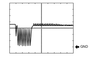
Waveform 1 (Reference)
Item Content Terminal No. (Symbol) I20-1 (S1) - I20-2 (E1)
I20-3 (S2) - I20-4 (E2)
I20-6 (S3) - I20-7 (E3)
I20-8 (S4) - I20-9 (E4)
Tool Setting 2 V/DIV., 100 μsec./DIV. Condition
-
Power switch on (IG)
-
Combination switch assembly (clearance sonar main switch) on
-
Shift lever in R
Item Content Terminal No. (Symbol) I20-19 (S5) - I20-20 (E5)
I20-21 (S6) - I20-22 (E6)
Tool Setting 2 V/DIV., 100 μsec./DIV. Condition
-
Power switch on (IG)
-
Combination switch assembly (clearance sonar main switch) on
-
Shift lever in R
-
Power switch on (IG)
-
Combination switch assembly (clearance sonar main switch) on
-
Shift lever in any position other than P or R
-
Less than approximately 15 km/h (9 mph) if vehicle speed increasing
-
Less than approximately 10 km/h (6 mph) if vehicle speed decreasing
Item Content Terminal No. (Symbol) I20-23 (S7) - I20-24 (E7)
I20-25 (S8) - I20-26 (E8)
Tool Setting 2 V/DIV., 100 μsec./DIV. Condition
-
Power switch on (IG)
-
Combination switch assembly (clearance sonar main switch) on
-
Shift lever in any position other than P or R
-
Less than approximately 15 km/h (9 mph) if vehicle speed increasing
-
Less than approximately 10 km/h (6 mph) if vehicle speed decreasing
-
-
-
Using an oscilloscope, check waveform 2.
-
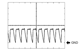
Waveform 2 (Reference)
Item Content Terminal No. (Symbol) I20-11 (CBZ) - I20-10 (EF) Tool Setting 2 V/DIV., 500 μsec./DIV. Condition Buzzer sounding Tech Tips
The amplitude of the waveform changes according to the set volume.
-
-