LEXUS PARKING ASSIST-SENSOR SYSTEM OPERATION CHECK
-
MALFUNCTION DISPLAY (MULTI-INFORMATION DISPLAY)
-
Open circuit indication
-
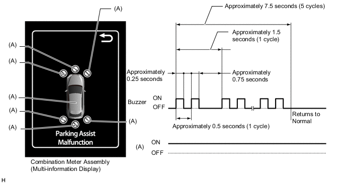
If there is an open circuit between a No. 1 ultrasonic sensor, No. 2 ultrasonic sensor, No. 3 ultrasonic sensor or No. 4 ultrasonic sensor and the clearance warning ECU assembly or a sensor is malfunctioning, the malfunction is displayed as shown in the illustration.
Tech Tips
-
If a sensor has an open circuit, check for DTCs and troubleshoot according to each inspection procedure.
-
Buzzer sounding stops at 5 cycles. also blinking of (A) indicator stops, after returns to normal.
-
-
-
Frozen indication
-
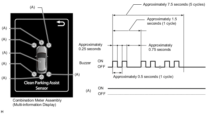
If a sensor is covered with foreign matter, such as mud or snow, the affected sensor is displayed as shown in the illustration.
Tech Tips
-
If a frozen indication is displayed, proceed to "Sensor Frozen Indication (Dirty or Frozen)".
-
Buzzer sounding stops at 5 cycles. also blinking of (A) indicator stops, after returns to normal.
-
-
-
-
MALFUNCTION DISPLAY (MULTI-DISPLAY)
-
Open circuit indication
-
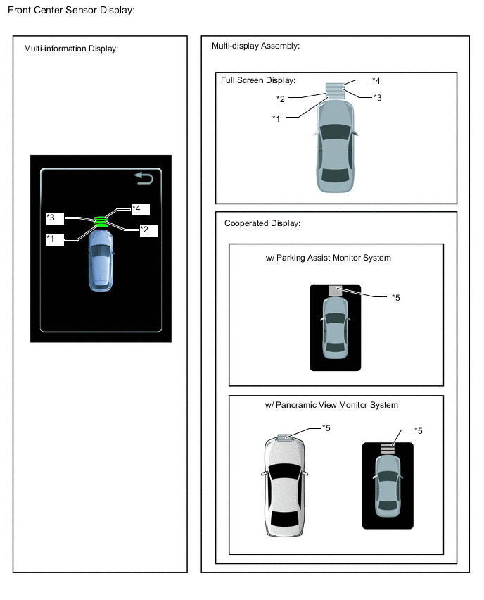
If there is an open circuit between the No. 1 ultrasonic sensor, No. 2 ultrasonic sensor, No. 3 ultrasonic sensor or No. 4 ultrasonic sensor and the clearance warning ECU assembly or a sensor is malfunctioning, the malfunction is displayed as shown in the illustration.
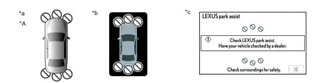
*A w/ Panoramic View Monitor System - - *a When panoramic view monitor system operates *b When parking assist monitor system operates *c When full screen displays - - Tech Tips
If a sensor has an open circuit, check for DTCs and troubleshoot according to each inspection procedure.
-
-
Frozen indication
-
If a sensor is covered with foreign matter, such as mud or snow, the affected sensor is displayed as shown in the illustration.
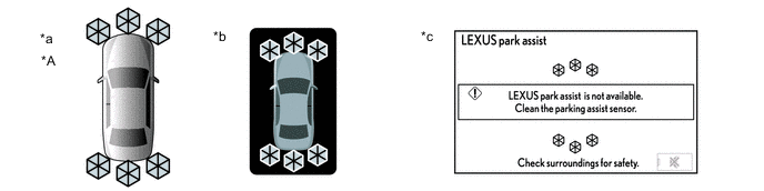
*A w/ Panoramic View Monitor System - - *a When panoramic view monitor system operates *b When parking assist monitor system operates *c When full screen displays - - Tech Tips
-
If a frozen indication is displayed, proceed to "Sensor Frozen Indication (Dirty or Frozen)".
-
Check for DTCs and troubleshoot according to each inspection procedure after confirming that the sensor is not covered with foreign matter.
-
-
-
-
DETECTION RANGE MEASUREMENT AND DISPLAY INSPECTION
Note
The following measurement and inspection will be performed with the shift lever in a position other than P. Be sure to apply the parking lever and depress the brake pedal firmly to prevent the vehicle from moving.
-
Turn the power switch on (IG).
-
Turn the combination switch assembly (clearance sonar main switch) on.
-
Detection range measurement:
-
Move the shift lever according to the table below.
Measurement Area Shift Lever Position Front Corner In any position other than P Front Center In any position other than P or R Rear Corner R Rear Center -
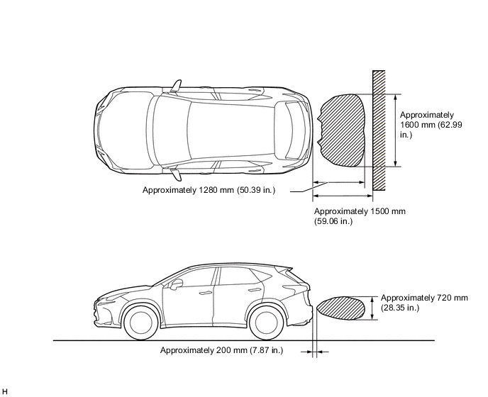
Move a 60 mm (2.4 in.) diameter pole near each sensor to measure its detection range. When measuring the *4: Longest-range detection of the front center sensor and the rear center sensor, use a wall or equivalent.
Note
These detection ranges are applicable when positioning the 60 mm (2.4 in.) diameter pole parallel or perpendicular to the ground. The detection range varies depending on the measuring method and type of obstacle (such as walls).
Tech Tips
Have an assistant move the pole.
Figure 1. Corner Sensor Detection Range
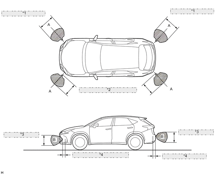
*1 Approximately 900 mm (35.43 in.) *2 Approximately 600 mm (23.62 in.) *3 Approximately 550 mm (21.65 in.) *4 Approximately 200 mm (7.87 in.) Note
The No. 1 ultrasonic sensor side view detection range (hatched area labeled (B)) represents the cross section of the top view detection range (A). The hatched area (B) does not represent the entire side view detection range.
Figure 2. Front Center Sensor Detection Range
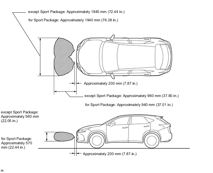
Figure 3. Rear Center Sensor Detection Range
-
-
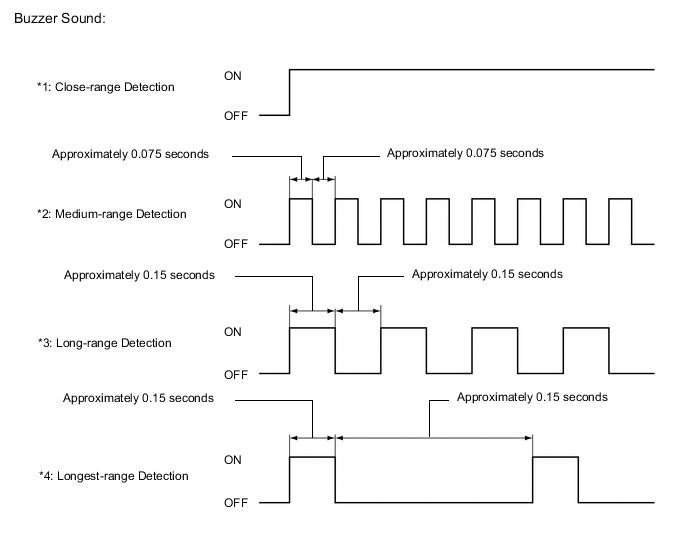
Front center sensor display and buzzer operation check
-
When the No. 1 ultrasonic sensors (front center sensor) have detected an obstacle, check the display and check that the buzzer sounds.
Operation Condition Power switch Clearance Sonar Main Switch Shift Lever Position Vehicle Speed On (IG) On In any position other than P or R
-
Less than approximately 15 km/h (9 mph) if speed is increasing
-
Less than approximately 10 km/h (6 mph) if speed is decreasing
Tech Tips
Ultrasonic waves are used to measure the detection range; however, the detection range may vary depending on the ambient temperature.
-
-
-
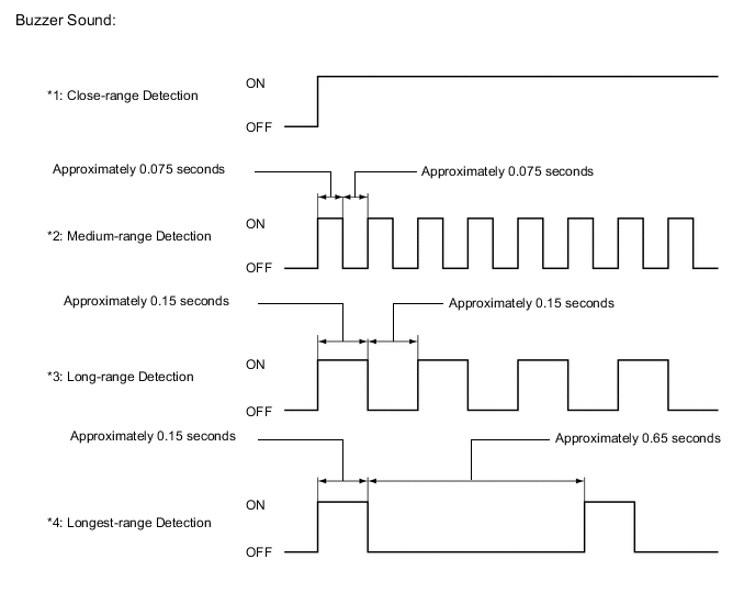
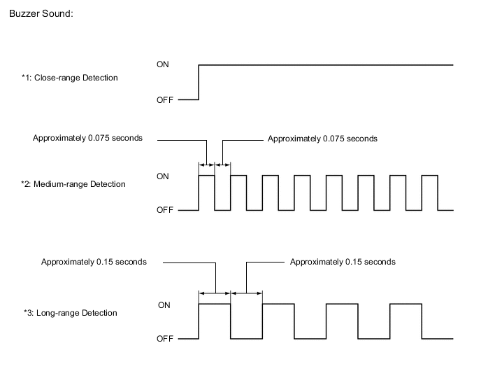
Front corner sensor display and buzzer operation check
-
When the No. 2 ultrasonic sensors (front corner sensor) have detected an obstacle, check the displays and check that the buzzer sounds.
Operation Condition Power switch Clearance Sonar Main Switch Shift Lever Position Vehicle Speed On (IG) On In any position other than P or R
-
Less than approximately 15 km/h (9 mph) if speed is increasing
-
Less than approximately 10 km/h (6 mph) if speed is decreasing
On (IG) On R - 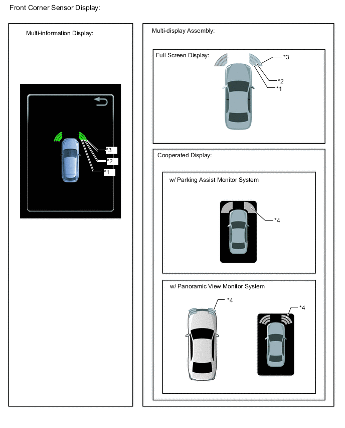
Tech Tips
Ultrasonic waves are used to measure the detection range; however, the detection range may vary depending on the ambient temperature.
-
-
-
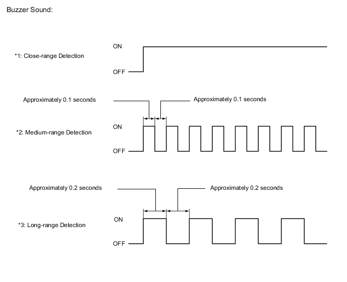
Rear corner sensor display and buzzer operation check
-
When the No. 3 ultrasonic sensors (rear corner sensor) have detected an obstacle, check the display and check that the buzzer sounds.
Operation Condition Power switch Clearance Sonar Main Switch Shift Lever Position Vehicle Speed On (IG) On R - 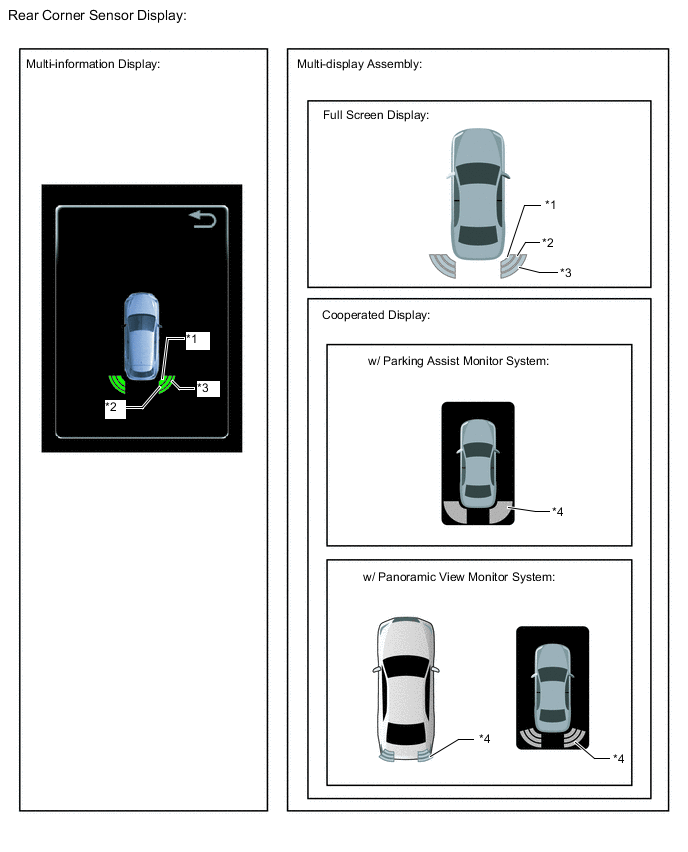
Tech Tips
Ultrasonic waves are used to measure the detection range; however, the detection range may vary depending on the ambient temperature.
-
-
Rear center sensor display and buzzer operation check
-
When the No. 4 ultrasonic sensors (rear center sensor) have detected an obstacle, check the display and check that the buzzer sounds.
Operation Condition Power switch Clearance Sonar Main Switch Shift Lever Position Vehicle Speed On (IG) On R - 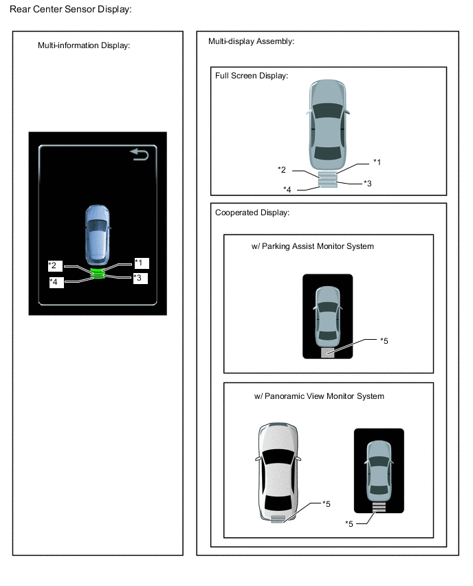
Tech Tips
Ultrasonic waves are used to measure the detection range; however, the detection range may vary depending on the ambient temperature.
-
-