INTELLIGENT CLEARANCE SONAR SYSTEM, Diagnostic DTC:C1625
| DTC Code | DTC Name |
|---|---|
| C1625 | Open or Short in Steering Angle Sensor +B |
DESCRIPTION
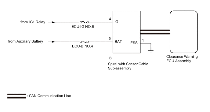
This DTC is stored if the clearance warning ECU assembly receives a signal via CAN communication from the spiral with sensor cable sub-assembly that indicates a power supply problem.
| DTC No. | Detection Item | DTC Detection Condition | Trouble Area |
|---|---|---|---|
| C1625 | Open or Short in Steering Angle Sensor +B | Open or short in spiral with sensor cable sub-assembly power source |
|
WIRING DIAGRAM
CAUTION / NOTICE / HINT
Note
-
After turning the power switch off, waiting time may be required before disconnecting the cable from the negative (-) auxiliary battery terminal. Therefore make sure to read the disconnecting the cable from the negative (-) auxiliary battery terminal notices before proceeding with work.
-
After replacing an ultrasonic sensor or the clearance warning ECU assembly, perform the necessary procedures (adjustment, calibration, initialization or registration).
-
Inspect the fuses for circuits related to this system before performing the following procedure.
PROCEDURE
-
CHECK HARNESS AND CONNECTOR (SPIRAL WITH SENSOR CABLE SUB-ASSEMBLY POWER SOURCE)
-
Disconnect the I6 spiral with sensor cable sub-assembly connector.
-
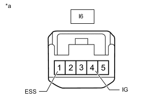
*a Front view of wire harness connector
(to Spiral with Sensor Cable Sub-assembly)
Measure the voltage according to the value(s) in the table below.
Standard Voltage Tester Connection Condition Specified Condition I6-4 (IG) - I6-1 (ESS) Power switch on (IG) 11 to 14 V Result Proceed to OK NG
NG 
REPAIR OR REPLACE HARNESS OR CONNECTOR
OK 
-
-
CHECK HARNESS AND CONNECTOR (SPIRAL WITH SENSOR CABLE SUB-ASSEMBLY POWER SOURCE)
-
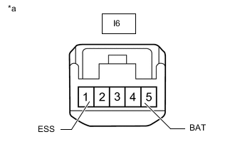
*a Front view of wire harness connector
(to Spiral with Sensor Cable Sub-assembly)
Measure the resistance according to the value(s) in the table below.
Standard Resistance Tester Connection Condition Specified Condition I6-1 (ESS) - Body ground Always Below 1 Ω -
Measure the voltage according to the value(s) in the table below.
Standard Voltage Tester Connection Condition Specified Condition I6-5 (BAT) - I6-1 (ESS) Power switch off 11 to 14 V Result Proceed to OK NG
OK
REPLACE SPIRAL WITH SENSOR CABLE SUB-ASSEMBLY Click here
NG
REPAIR OR REPLACE HARNESS OR CONNECTOR
-