MAYDAY BATTERY INSTALLATION
PROCEDURE
-
INSTALL MAYDAY BATTERY
CAUTION:
-
Do not reuse dropped or damaged parts.
-
Wear gloves when contacting parts that have been dropped from a height of 1 m or higher.
-
There may be an internal short or the temperature may increase to 100°C or higher due to the shock from being dropped.
-
If an internal short has occurred, gas may be discharged. Therefore, if there is even a small amount of heat, maintain a distance of 3 m or more from the vehicle and wait for 1 minute or longer.
-
w/ Telematics Transceiver for G-BOOK
-
Connect the connector and temporarily replace the mayday battery in the vehicle.
-
-
w/ Telematics Transceiver except G-BOOK
-
Connect the connector and install the mobilephone battery as shown in the illustration.
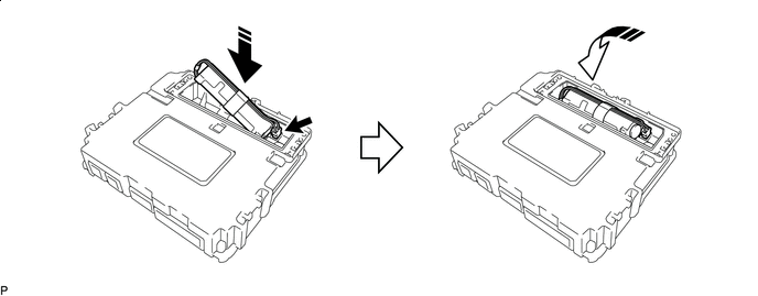

Install in this Direction (1) 
Install in this Direction (2) Note
Check that the connector is securely connected.
-
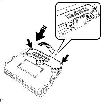
Install in this Direction (1) Install in this Direction (2) Insert the 3 guides and attach the 2 claws as shown in the illustration.
-
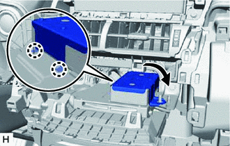
Install the battery cover with the 2 screws.
Note
Check that the battery cover does not lift up.
-
-
-
INSTALL TELEMATICS TRANSCEIVER (w/ Telematics Transceiver except G-BOOK)
-
INSTALL NO. 3 TELEPHONE BRACKET (w/ Telematics Transceiver for G-BOOK)
-
Attach the 2 claws and install the bracket as shown in the illustration.
-
Install the No. 3 telephone bracket with the nut.
-
-
INSTALL AIR CONDITIONING CONTROL ASSEMBLY
-
INSTALL CENTER INSTRUMENT CLUSTER FINISH PANEL ASSEMBLY
-
INSTALL NO. 2 INSTRUMENT PANEL SAFETY PAD SUB-ASSEMBLY
-
INSTALL NO. 1 SWITCH HOLE BASE
-
INSTALL LOWER NO. 1 INSTRUMENT PANEL FINISH PANEL
-
INSTALL NO. 1 INSTRUMENT PANEL UNDER COVER SUB-ASSEMBLY
-
INSTALL NO. 1 INSTRUMENT PANEL SAFETY PAD SUB-ASSEMBLY
-
INSTALL INSTRUMENT SIDE PANEL LH
-
INSTALL INSTRUMENT SIDE PANEL RH
-
INSTALL UPPER NO. 2 CONSOLE PANEL GARNISH
-
INSTALL UPPER NO. 1 CONSOLE PANEL GARNISH
-
INSTALL UPPER REAR CONSOLE PANEL
-
INSTALL CONSOLE ARMREST ASSEMBLY
-
INSTALL COWL SIDE TRIM BOARD RH (for RHD)
-
INSTALL DOOR SCUFF PLATE ASSEMBLY RH (for RHD)
-
CONNECT CABLE TO NEGATIVE AUXILIARY BATTERY TERMINAL
Note
When disconnecting the cable, some systems need to be initialized after the cable is reconnected.
-
INSTALL DECK FLOOR BOX LH (w/ Spare Tire)
-
INSTALL REAR DECK FLOOR BOX (w/ Spare Tire)
-
INSTALL NO. 3 DECK BOARD SUB-ASSEMBLY
-
INSTALL DECK BOARD ASSEMBLY