TELEMATICS TRANSCEIVER INSTALLATION
PROCEDURE
-
INSTALL NO. 2 TELEPHONE BRACKET (w/ Telematics Transceiver for G-BOOK)
-
Install the No. 2 telephone bracket with the bolt.
-
-
INSTALL NO. 1 TELEPHONE BRACKET (w/ Telematics Transceiver for G-BOOK)
-
Install the No. 1 telephone bracket with the bolt.
-
-
INSTALL MAYDAY BATTERY (w/ Telematics Transceiver except G-BOOK)
-
INSTALL TELEMATICS TRANSCEIVER
-
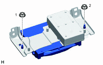
w/ Telematics Transceiver for G-BOOK
-
Install the telematics transceiver with the 2 nuts.
Tech Tips
Tighten the screws in the order shown in the illustration.
-
-
w/ Telematics Transceiver except G-BOOK
-
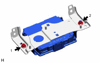
Install the telematics transceiver with the 2 nuts.
Tech Tips
Tighten the screws in the order shown in the illustration.
-
-
-
INSTALL TELEMATICS TRANSCEIVER WITH BRACKET
-
w/ Telematics Transceiver for G-BOOK
-
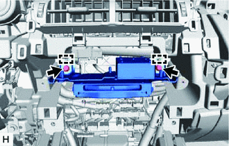
Connect each connector and temporarily install the telematics transceiver with bracket by attaching the 2 guides of the telematics transceiver with bracket to the instrument panel.
-
Install the telematics transceiver with bracket with the 2 bolts.
Tech Tips
Tighten the screws in the order shown in the illustration.
-
-
w/ Telematics Transceiver except G-BOOK
-
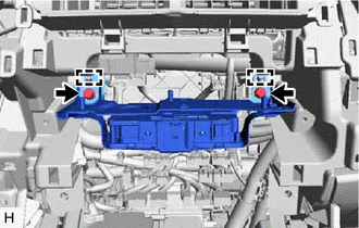
Connect each connector and temporarily install the telematics transceiver with bracket by attaching the 2 guides of the telematics transceiver with bracket to the instrument panel.
-
Install the telematics transceiver with bracket with the 2 bolts.
Tech Tips
Tighten the screws in the order shown in the illustration.
-
-
-
INSTALL RADIO RECEIVER ASSEMBLY WITH BRACKET
-
INSTALL AIR CONDITIONING CONTROL ASSEMBLY
-
INSTALL UPPER REAR CONSOLE PANEL SUB-ASSEMBLY
-
INSTALL SHIFT LEVER KNOB SUB-ASSEMBLY
-
INSTALL CENTER INSTRUMENT CLUSTER FINISH PANEL ASSEMBLY
-
INSTALL NO. 2 INSTRUMENT PANEL SAFETY PAD SUB-ASSEMBLY
-
INSTALL NO. 1 SWITCH HOLE BASE
-
INSTALL LOWER NO. 1 INSTRUMENT PANEL FINISH PANEL
-
INSTALL NO. 1 INSTRUMENT PANEL UNDER COVER SUB-ASSEMBLY
-
INSTALL NO. 1 INSTRUMENT PANEL SAFETY PAD SUB-ASSEMBLY
-
INSTALL INSTRUMENT SIDE PANEL LH
-
INSTALL INSTRUMENT SIDE PANEL RH
-
INSTALL UPPER NO. 2 CONSOLE PANEL GARNISH
-
INSTALL UPPER NO. 1 CONSOLE PANEL GARNISH
-
INSTALL UPPER REAR CONSOLE PANEL
-
INSTALL CONSOLE ARMREST ASSEMBLY
-
INSTALL COWL SIDE TRIM BOARD RH (for RHD)
-
INSTALL DOOR SCUFF PLATE ASSEMBLY RH (for RHD)
-
INSTALL MULTI-DISPLAY ASSEMBLY WITH BRACKET
-
INSTALL INSTRUMENT PANEL FINISH PLATE
-
CONNECT CABLE TO NEGATIVE AUXILIARY BATTERY TERMINAL
Note
When disconnecting the cable, some systems need to be initialized after the cable is reconnected.
-
CHECK SRS WARNING LIGHT
-
INSTALL DECK FLOOR BOX LH (w/ Spare Tire)
-
INSTALL REAR DECK FLOOR BOX (w/ Spare Tire)
-
INSTALL NO. 3 DECK BOARD SUB-ASSEMBLY
-
INSTALL DECK BOARD ASSEMBLY