TELEMATICS SYSTEM(w/ Telematics Transceiver except G-BOOK), Diagnostic DTC:B15C4
| DTC Code | DTC Name |
|---|---|
| B15C4 | SRS Communication Error |
DESCRIPTION
If the telematics transceiver detects an error in communication between itself and the airbag ECU assembly as a result of a self check, this DTC will be stored.
| DTC No. | Detection Item | DTC Detection Condition | Trouble Area |
|---|---|---|---|
| B15C4 | SRS Communication Error | The telematics transceiver detects an error in signals from the airbag ECU assembly when power switch is on (IG). |
|
WIRING DIAGRAM
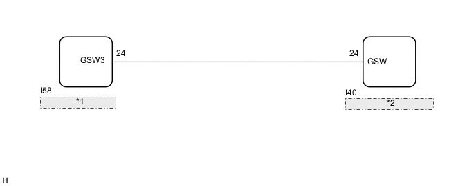
| *1 | Airbag ECU Assembly |
| *2 | Telematics Transceiver |
CAUTION / NOTICE / HINT
Note
-
Depending on the parts that are replaced during vehicle inspection or maintenance, performing initialization, registration or calibration may be needed. Refer to Registration for Telematics System.
-
This vehicle is equipped with a Supplemental Restraint System (SRS) which includes components such as airbags. Before servicing (including removal or installation of parts), be sure to read the precaution for Supplemental Restraint System.
-
After turning the power switch off, waiting time may be required before disconnecting the cable from the negative (-) auxiliary battery terminal. Therefore, make sure to read the disconnecting the cable from the negative (-) auxiliary battery terminal notices before proceeding with work.
-
When replacing the telephone transceiver assembly, make sure to replace it with a new one.
PROCEDURE
-
CHECK FOR DTC (AIRBAG SYSTEM)
-
Turn the power switch off.
-
Connect the GTS to the DLC3.
-
Turn the power switch on (IG) and wait for 20 seconds.
-
Turn the GTS on.
-
Check if airbag system DTCs are output.
Body Electrical > SRS Airbag > Trouble CodesResult Result Proceed to DTCs are not output A DTCs are output B
B 
GO TO AIRBAG SYSTEM Click here
A 
-
-
CHECK TELEMATICS TRANSCEIVER
-
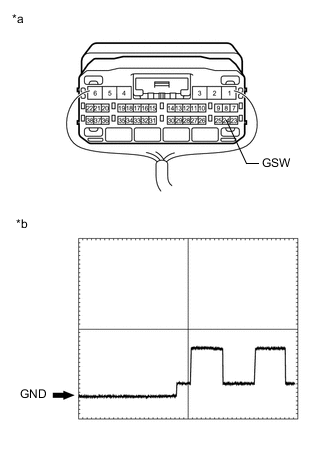
*a Component with harness connected
(Telematics Transceiver)
*b Waveform Measure the voltage according to the value(s) in the table below.
Standard Voltage Tester Connection Switch Condition Specified Condition 24 (GSW) - Body ground Power switch on (IG) Pulse generation (Refer to waveform) Reference Waveform Item Condition Tester connection 24 (GSW) - Body ground Tool setting 5.0 V/DIV., 20 ms/DIV. Vehicle condition Power switch on (IG) Result Proceed to OK NG
NG 
CHECK HARNESS AND CONNECTOR (TELEMATICS TRANSCEIVER - AIRBAG ECU ASSEMBLY) Click here
OK
-
-
REPLACE TELEMATICS TRANSCEIVER
-
Replace the telematics transceiver with a new one.
Result Proceed to NEXT
NEXT
PERFORM REGISTRATION Click here
-
-
CHECK HARNESS AND CONNECTOR (TELEMATICS TRANSCEIVER - AIRBAG ECU ASSEMBLY)
-
Disconnect the I40 telematics transceiver connector.
-
Disconnect the I58 airbag ECU assembly connector.
-
Measure the resistance according to the value(s) in the table below.
Standard Resistance Tester Connection Condition Specified Condition I40-24 (GSW) - I58-24 (GSW3) Always Below 1 Ω I40-24 (GSW) or I58-24 (GSW3) - Body ground Always 10 kΩ or higher Result Proceed to OK NG
OK
REPLACE AIRBAG ECU ASSEMBLY Click here
NG
REPAIR OR REPLACE HARNESS OR CONNECTOR
-