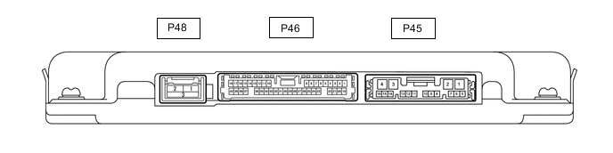
PANORAMIC VIEW MONITOR SYSTEM TERMINALS OF ECU
-
PARKING ASSIST ECU
-
Disconnect the P45 parking assist ECU connector.
-
Measure the voltage and resistance according to the value(s) in the table below.
Terminal No. (Symbol) Wiring Color Terminal Description Condition Specified Condition P45-1 (+B) - P45-4 (GND1) L - W-B Power source signal Power switch off 11 to 14 V P45-4 (GND1) - Body ground W-B - Body ground Ground Always Below 1 Ω P45-3 (IG) - P45-4 (GND1) G - W-B IG power source signal Power switch on (IG) 11 to 14 V Power switch off Below 1 V P45-2 (ACC) - P45-4 (GND1) L - W-B ACC power source signal Power switch on (ACC) 11 to 14 V Power switch off Below 1 V -
Reconnect the P45 parking assist ECU connector.
-
Measure the voltage, resistance and waveform according to the value(s) in the table below.
Terminal No. (Symbol) Wiring Color Terminal Description Condition Specified Condition P46-29 (CV+) - P46-31 (SGND) W - Shielded Rear television camera assembly display signal input Power switch on (IG), No. 2 combination switch assembly (panoramic view monitor main switch) on, camera lens not covered, displaying image Pulse generation (See waveform 1) Power switch on (IG), No. 2 combination switch assembly (panoramic view monitor main switch) on, camera lens covered, blacking out screen Pulse generation (See waveform 2) P46-33 (CB+) - P46-31 (SGND) B - Shielded Power source to rear television camera Power switch on (IG) 5.5 to 7.05 V P46-6 (RSW+) - P45-4 (GND1) P - W-B Terminal required by law Panoramic image being displayed 0 to 2 V Panoramic image not being displayed 5.5 to 7.05 V P45-15 (BLSW) - Body ground R - Body ground No. 2 combination switch assembly (panoramic view monitor main switch) switch signal Power switch on (IG), No. 2 combination switch assembly (panoramic view monitor main switch) off 5.5 to 6.5 V Power switch on (IG), No. 2 combination switch assembly (panoramic view monitor main switch) on Below 1 V P46-31 (SGND) - P45-4 (GND1) Shielded - W-B Rear television camera assembly ground (shield) Always Below 1 Ω P46-30 (CV-) - P46-31 (SGND) R - Shielded Rear television camera assembly ground Always Below 1 Ω P46-34 (LCV-) - P46-11 (SGND) W - Shielded Side television camera assembly LH ground Always Below 1 Ω P46-10 (LCV+) - P46-35 (LGND) R - G Side television camera assembly LH display signal input Power switch on (IG), No. 2 combination switch assembly (panoramic view monitor main switch) on, camera lens not covered, displaying image Pulse generation (See waveform 1) Power switch on (IG), No. 2 combination switch assembly (panoramic view monitor main switch) on, camera lens covered, blacking out screen Pulse generation (See waveform 2) P46-11 (SGND) - P45-4 (GND1) Shielded - W-B Side television camera assembly LH ground (shield) Always Below 1 Ω P46-12 (LCB+) - P46-11 (SGND) B - Shielded Power source to side television camera assembly LH Power switch on (IG) 5.5 to 7.05 V P46-13 (BCV-) - P46-14 (SGND) W - Shielded Front television camera assembly ground Always Below 1 Ω P46-36 (BCV+) - P46-14 (SGND) R - Shielded Front television camera assembly display signal input Waveform 1: Power switch on (IG), No. 2 combination switch assembly (panoramic view monitor main switch) on, camera lens not covered, displaying image Pulse generation (See waveform 1) Waveform 2: Power switch on (IG), No. 2 combination switch assembly (panoramic view monitor main switch) on, camera lens covered, blacking out screen Pulse generation (See waveform 2) P46-14 (SGND) - P45-4 (GND1) Shielded - W-B Front television camera assembly ground (shield) Always Below 1 Ω P46-15 (BCB+) - P46-14 (SGND) B - Shielded Power source to front television camera Power switch on (IG) 5.5 to 7.05 V P46-16 (RCV-) - P46-39 (SGND) W - Shielded Side television camera assembly RH ground Always Below 1 Ω P46-38 (RCV+) - P46-39 (SGND) R - Shielded Side television camera assembly RH display signal input Waveform 1: Power switch on (IG), No. 2 combination switch assembly (panoramic view monitor main switch) on, camera lens not covered, displaying image Pulse generation (See waveform 1) Waveform 2: Power switch on (IG), No. 2 combination switch assembly (panoramic view monitor main switch) on, camera lens covered, blacking out screen Pulse generation (See waveform 2) P46-39 (SGND) - P45-4 (GND1) Shielded - W-B Side television camera assembly RH ground (shield) Always Below 1 Ω P46-40 (RCB+) - P46-39 (SGND) B - Shielded Power source to side television camera assembly RH Power switch on (IG) 5.5 to 7.05 V -
Using an oscilloscope, check the waveform.
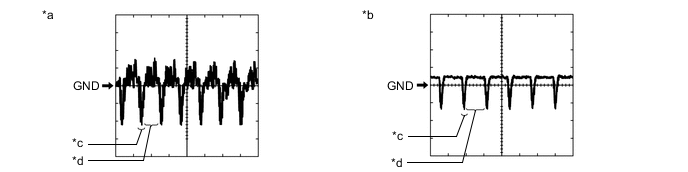
*a Waveform 1 *b Waveform 2 *c Synchronization Signal *d Video Waveform
-
Waveform 1
Measurement Condition Item Content Terminal No. (Symbol)
-
P46-29 (CV+) - P46-31 (SGND)
-
P46-10 (LCV+) - P46-11 (SGND)
-
P46-36 (BCV+) - P46-14 (SGND)
-
P46-38 (RCV+) - P46-39 (SGND)
Tool Setting 200 mV/DIV., 50 μsec./DIV. Condition
-
Waveform 1: Power switch on (IG), No. 2 combination switch assembly (panoramic view monitor main switch) on, camera lens not covered, displaying image
-
Waveform 2: Power switch on (IG), No. 2 combination switch assembly (panoramic view monitor main switch) on, camera lens covered, blacking out screen
Tech Tips
-
The video waveform changes according to the image sent by the television camera assembly.
-
The video waveform is constantly output when the power switch is on (ACC).
-
-
-
-
RADIO RECEIVER ASSEMBLY (w/ Audio and Visual System [for 10.3 Inch Display])
-
RADIO RECEIVER ASSEMBLY (w/ Navigation System)