AUDIO AND VISUAL SYSTEM(except 8 Speakers) Microphone Circuit between Microphone and Radio Receiver
DESCRIPTION
-
The radio receiver assembly and map light assembly (telephone microphone assembly) are connected to each other using the microphone connection detection signal lines.
-
Using this circuit, the radio receiver assembly sends power to the map light assembly (telephone microphone assembly), and the map light assembly (telephone microphone assembly) sends microphone signals to the radio receiver assembly.
WIRING DIAGRAM
-
w/o Telematics Transceiver
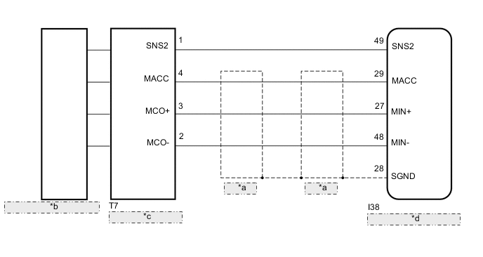
*a Shielded *b Telephone Microphone Assembly *c Map Light Assembly *d Radio Receiver Assembly -
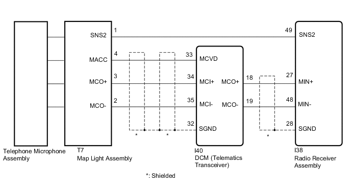
w/ Telematics Transceiver
CAUTION / NOTICE / HINT
Note
Depending on the parts that are replaced during vehicle inspection or maintenance, performing initialization, registration or calibration may be needed. Refer to precaution for audio and visual system.
PROCEDURE
-
CHECK MICROPHONE (OPERATION CHECK)
-
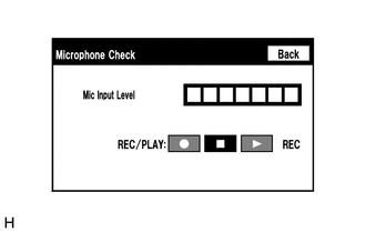
Enter the "Microphone Check" screen. Refer to Check Mic & Voice Recognition in Operation Check.
-
When a voice is input into the microphone, check that the microphone input level meter changes according to the input voice.
-
Push the recording switch and perform voice recording.
Tech Tips
-
Select the recording switch with the blower motor of the air conditioning system stopped. If an outlet of the air conditioning system is facing the microphone, noise may be recorded.
-
Voice can be recorded for up to 5 seconds.
-
-
Check that the recording indicator remains on while recording and that the recorded voice is played normally without noise or distortion.
OK All check results are normal. Result Proceed to OK NG
OK 
REPLACE RADIO RECEIVER ASSEMBLY Click here
NG 
-
-
CONFIRM MODEL
-
Choose the model to be inspected.
Result Result Proceed to w/o Telematics Transceiver A w/ Telematics Transceiver B
B 
CHECK HARNESS AND CONNECTOR (RADIO RECEIVER ASSEMBLY - MAP LIGHT ASSEMBLY) Click here
A
-
-
CHECK HARNESS AND CONNECTOR (RADIO RECEIVER ASSEMBLY - MAP LIGHT ASSEMBLY)
-
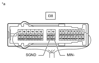
Disconnect the I38 radio receiver assembly connector.
-
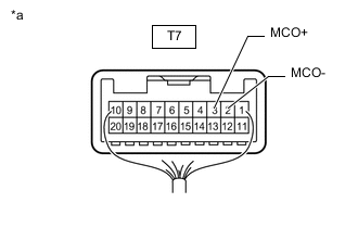
Disconnect the T7 map light assembly connector.
-
Measure the resistance according to the value(s) in the table below.
Standard Resistance Tester Connection Condition Specified Condition I38-49 (SNS2) - T7-1 (SNS2) Always Below 1 Ω I38-29 (MACC) - T7-4 (MACC) Always Below 1 Ω I38-27 (MIN+) - T7-3 (MCO+) Always Below 1 Ω I38-48 (MIN-) - T7-2 (MCO-) Always Below 1 Ω I38-28 (SGND) - Body ground Always 10 kΩ or higher I38-49 (SNS2) or T7-1 (SNS2) - Body ground Always 10 kΩ or higher I38-29 (MACC) or T7-4 (MACC) - Body ground Always 10 kΩ or higher I38-27 (MIN+) or T7-3 (MCO+) - Body ground Always 10 kΩ or higher I38-48 (MIN-) or T7-2 (MCO-) - Body ground Always 10 kΩ or higher Result Proceed to OK NG
NG
REPAIR OR REPLACE HARNESS OR CONNECTOR
OK
-
-
CHECK RADIO RECEIVER ASSEMBLY
-
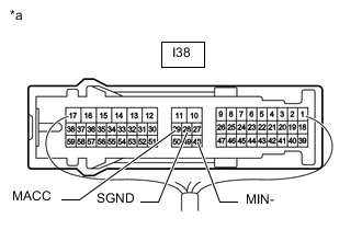
*a Component with harness connected
(Radio Receiver Assembly)
Measure the resistance according to the value(s) in the table below.
Standard Resistance Tester Connection Condition Specified Condition I38-28 (SGND) - Body ground Always Below 1 Ω I38-48 (MIN-) - Body ground Always Below 1 Ω -
Measure the voltage according to the value(s) in the table below.
Standard Voltage Tester Connection Switch Condition Specified Condition I38-29 (MACC) - Body ground Power switch on (ACC) 4 to 6 V Result Proceed to OK NG
NG
REPLACE RADIO RECEIVER ASSEMBLY Click here
OK
-
-
INSPECT MAP LIGHT ASSEMBLY (TELEPHONE MICROPHONE ASSEMBLY)
-
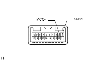
Remove the map light assembly (telephone microphone assembly).
-
Measure the resistance according to the value(s) in the table below.
Standard Resistance Tester Connection Condition Specified Condition 1 (SNS2) - 2 (MCO-) Always Below 1 Ω Result Proceed to OK NG
NG
GO TO STEP 7 Click here
OK
-
-
CHECK MAP LIGHT ASSEMBLY
-
*a Component with harness connected
(Map Light Assembly)
Reconnect the radio receiver assembly connector.
-
Reconnect the map light assembly connector.
-
Turn the power switch on (ACC).
-
Connect an oscilloscope to terminals T7-3 (MCO+) and T7-2 (MCO-) of the map light assembly connector.
-
Check the waveform of the telephone microphone assembly using the oscilloscope.
Result Result Proceed to A waveform synchronized with the voice input to the map light assembly is not output. A A waveform synchronized with the voice input to the map light assembly is output. B
B
PROCEED TO NEXT SUSPECTED AREA SHOWN IN PROBLEM SYMPTOMS TABLE Click here
A
-
-
CHECK TELEPHONE MICROPHONE ASSEMBLY
-
Replace the telephone microphone assembly.
-
Check if the same malfunction recurs.
OK Malfunction does not recur (returns to normal). Result Proceed to OK NG
OK
END (TELEPHONE MICROPHONE ASSEMBLY IS DEFECTIVE)
NG
REPLACE MAP LIGHT ASSEMBLY Click here
-
-
CHECK HARNESS AND CONNECTOR (RADIO RECEIVER ASSEMBLY - MAP LIGHT ASSEMBLY)
-
Disconnect the I38 radio receiver assembly connector.
-
Disconnect the T7 map light assembly connector.
-
Measure the resistance according to the value(s) in the table below.
Standard Resistance Tester Connection Condition Specified Condition I38-49 (SNS2) - T7-1 (SNS2) Always Below 1 Ω I38-49 (SNS2) or T7-1 (SNS2) - Body ground Always 10 kΩ or higher Result Proceed to OK NG
NG
REPAIR OR REPLACE HARNESS OR CONNECTOR
OK
-
-
CHECK HARNESS AND CONNECTOR (RADIO RECEIVER ASSEMBLY - DCM [TELEMATICS TRANSCEIVER])
-
Disconnect the I38 radio receiver assembly connector.
-
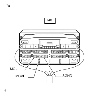
Disconnect the I40 DCM (telematics transceiver) connector.
-
Measure the resistance according to the value(s) in the table below.
Standard Resistance Tester Connection Condition Specified Condition I38-27 (MIN+) - I40-18 (MCO+) Always Below 1 Ω I38-48 (MIN-) - I40-19 (MCO-) Always Below 1 Ω I38-28 (SGND) - Body ground Always 10 kΩ or higher I38-27 (MIN+) or I40-18 (MCO+) - Body ground Always 10 kΩ or higher I38-48 (MIN-) or I40-19 (MCO-) - Body ground Always 10 kΩ or higher Result Proceed to OK NG
NG
REPAIR OR REPLACE HARNESS OR CONNECTOR
OK
-
-
CHECK HARNESS AND CONNECTOR (DCM [TELEMATICS TRANSCEIVER] - MAP LIGHT ASSEMBLY)
-
Disconnect the I40 DCM (telematics transceiver) connector.
-
Disconnect the T7 map light assembly connector.
-
Measure the resistance according to the value(s) in the table below.
Standard Resistance Tester Connection Condition Specified Condition I40-33 (MCVD) - T7-4 (MACC) Always Below 1 Ω I40-34 (MCI+) - T7-3 (MCO+) Always Below 1 Ω I40-35 (MCI-) - T7-2 (MCO-) Always Below 1 Ω I40-32 (SGND) - Body ground Always 10 kΩ or higher I40-33 (MCVD) or T7-4 (MACC) - Body ground Always 10 kΩ or higher I40-34 (MCI+) or T7-3 (MCO+) - Body ground Always 10 kΩ or higher I40-35 (MCI-) or T7-2 (MCO-) - Body ground Always 10 kΩ or higher Result Proceed to OK NG
NG
REPAIR OR REPLACE HARNESS OR CONNECTOR
OK
-
-
CHECK RADIO RECEIVER ASSEMBLY
-
*a Component with harness connected
(Radio Receiver Assembly)
Measure the resistance according to the value(s) in the table below.
Standard Resistance Tester Connection Condition Specified Condition I38-28 (SGND) - Body ground Always Below 1 Ω I38-48 (MIN-) - Body ground Always Below 1 Ω Result Proceed to OK NG
NG
REPLACE RADIO RECEIVER ASSEMBLY Click here
OK
-
-
CHECK DCM (TELEMATICS TRANSCEIVER)
-
*a Component with harness connected
(DCM [Telematics Transceiver])
Measure the resistance according to the value(s) in the table below.
Standard Resistance Tester Connection Condition Specified Condition I40-32 (SGND) - Bodyground Always Below 1 Ω I40-35 (MCI-) - Bodyground Always Below 1 Ω -
Measure the voltage according to the value(s) in the table below.
Standard Voltage Tester Connection Switch Condition Specified Condition I40-33 (MCVD) - Body ground Power switch on (ACC) 4 to 6 V Result Proceed to OK NG
OK
GO TO STEP 5 Click here
NG
REPLACE DCM (TELEMATICS TRANSCEIVER) Click here
-