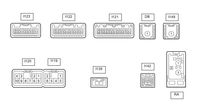
REAR VIEW MONITOR SYSTEM TERMINALS OF ECU
-
RADIO RECEIVER ASSEMBLY
-
Disconnect the I120 and I121 radio receiver assembly connectors.
-
Measure the voltage and resistance according to the value(s) in the table below.
Terminal No. (Symbol) Wiring Color Terminal Description Condition Specified Condition I120-3 (ACC1) - I120-7 (GND1) GR - W-B Power source (ACC) Power switch off Below 1 V Power switch on (ACC) 11 to 14 V I120-4 (+B1) - I120-7 (GND1) P - W-B Power source (+B) Power switch off 11 to 14 V I120-7 (GND1) - Body ground W-B - Body ground Ground Always Below 1 Ω I121-1 (IG) - I120-7 (GND1) P - W-B Power source (IG) Power switch off Below 1 V Power switch on (IG) 11 to 14 V -
Reconnect the I120 and I121 radio receiver assembly connectors.
-
Measure the voltage, resistance and waveform according to the value(s) in the table below.
Terminal No. (Symbol) Wiring Color Terminal Description Condition Specified Condition I122-11 (CA+) - I122-23 (CGND) B - Shielded Rear television camera assembly power source Power switch on (ACC) 5.5 to 7.05 V I122-12 (V+) - I122-23 (CGND) W - Shielded Video signal Power switch on (IG), shift lever in R, camera lens not covered, displaying an image+ Pulse generation
(See waveform 1)
Power switch on (IG), shift lever in R, camera lens covered, blacking out screen Pulse generation
(See waveform 2)
I122-23 (CGND) - Body ground Shielded - Body ground Shielded ground Always Below 1 Ω I122-24 (V-) - I122-23 (CGND) R - Shielded Ground Always Below 1 Ω -
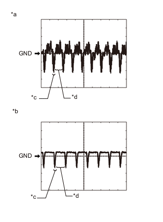
*a Waveform 1 *b Waveform 2 *c Synchronization Signal *d Video Waveform Reference (Oscilloscope waveform):
-
Waveform 1
Item Content Terminal No. (Symbol) I122-12 (V+) - I122-23 (CGND) Tool Setting 200 mV/DIV., 50 μsec./DIV. Condition Power switch on (IG), shift lever in R, camera lens not covered, displaying an image Tech Tips
The video waveform changes according to the image sent by the rear television camera assembly.
-
Waveform 2
Item Content Terminal No. (Symbol) I122-12 (V+) - I122-23 (CGND) Tool Setting 200 mV/DIV., 50 μsec./DIV. Condition Power switch on (IG), shift lever in R, camera lens covered, blacking out screen Tech Tips
The video waveform changes according to the image sent by the rear television camera assembly.
-
-