FRONT BRAKE FLEXIBLE HOSE INSTALLATION
CAUTION / NOTICE / HINT
Tech Tips
-
Use the same procedure for the RH and LH sides.
-
The following procedure is for the LH side.
Note
-
Since the RH side flexible hose and LH side flexible hose are not interchangeable, verify the part numbers when installing the front flexible hoses.
-
If the front flexible hoses are to be reused, connect them after checking the identification marks placed when each hose was disconnected.
PROCEDURE
-
INSTALL FRONT FLEXIBLE HOSE
-
Connect the flexible hose to the disc brake cylinder with a new gasket and new union bolt.
- Torque:
- 30.4 N*m { 310 kgf*cm, 22 ft.*lbf }
Tech Tips
Insert the flexible hose lock securely into the lock hole in the cylinder.
-
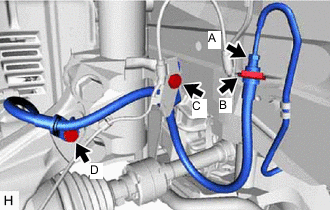
w/ AVS:
-
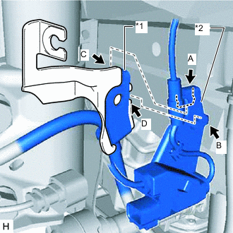
*1 Front Flexible Hose Bracket *2 Front Speed Sensor Clamp Set the flexible hose clamp on the flexible hose bracket.
-
Hook the hook labeled A of the front speed sensor bracket onto the part of the absorber bracket labeled C.
-
Insert the hook labeled B of the front speed sensor bracket into the part of the absorber bracket labeled D.
-
Install the No. 2 front flexible hose and front speed sensor bracket to the absorber bracket with the bolt.
- Torque:
- 18.8 N*m { 192 kgf*cm, 14 ft.*lbf }
-
Install the flexible hose bracket and speed sensor clamp to the steering knuckle with the bolt labeled D.
- Torque:
- 18.8 N*m { 192 kgf*cm, 14 ft.*lbf }
-
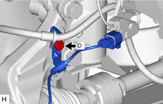
Install a new clip to the front flexible hose.
Note
Install the clip as far as it will go.
-
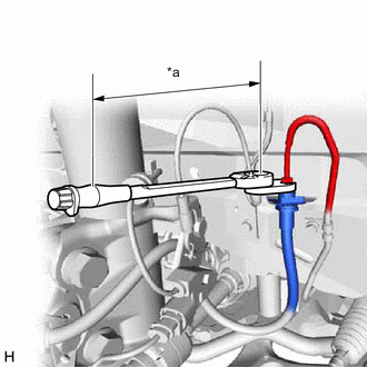
*a Torque Wrench Fulcrum Length Using a union nut wrench, connect the flexible hose to the brake tube labeled A while holding the flexible hose with a wrench.
- Torque:
- Specified tightening torque
- 15.2 N*m { 155 kgf*cm, 11 ft.*lbf }
Tech Tips
-
Calculate the torque wrench reading when changing the fulcrum length of the torque wrench.
-
When using union nut wrench (fulcrum length of 22 mm (0.8661 in.)) +torque wrench (fulcrum length of 162 mm(6.3779 in.)): 13.4 N*m (137 kgf*cm,10ft.*lbf)
Note
-
Do not bend or damage the brake tube.
-
Do not allow any foreign matter such as dirt and dust to enter the brake tube from the connecting point.
-
-
w/o AVS:
-
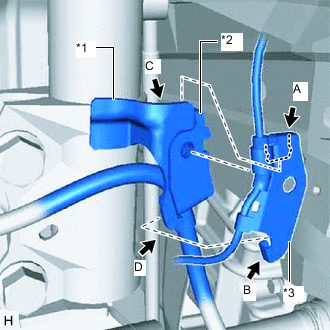
*1 Absorber Bracket *2 Flexible Hose Bracket *3 Front Speed Sensor Bracket Set the flexible hose clamp on the flexible hose bracket.
-
Hook the hook labeled A of the front speed sensor bracket onto the part of the absorber bracket labeled C.
-
Insert the hook labeled B of the front speed sensor bracket into the part of the absorber bracket labeled D.
-
Install the No. 2 front flexible hose and front speed sensor bracket to the absorber bracket with the bolt.
- Torque:
- 18.8 N*m { 192 kgf*cm, 14 ft.*lbf }
-
Install the No. 2 front flexible hose to the steering knuckle with the bolt labeled D.
- Torque:
- 18.8 N*m { 192 kgf*cm, 14 ft.*lbf }
-
Install a new clip to the front flexible hose.
Note
Install the clip as far as it will go.
-
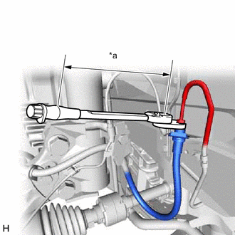
*a Torque Wrench Fulcrum Length Using a union nut wrench, connect the brake tube to the front flexible hose while holding the front flexible hose with a wrench.
- Torque:
- Specified tightening torque
- 15.2 N*m { 155 kgf*cm, 11 ft.*lbf }
Tech Tips
-
Calculate the torque wrench reading when changing the fulcrum length of the torque wrench.
-
When using union nut wrench (fulcrum length of 22 mm (0.8661 in.)) +torque wrench (fulcrum length of 162 mm(6.3779 in.)): 13.4 N*m (137 kgf*cm,10ft.*lbf)
Note
-
Do not bend or damage the brake tube.
-
Do not allow any foreign matter such as dirt and dust to enter the brake tube from the connecting parts.
-
-
-
CONNECT CABLE TO NEGATIVE AUXILIARY BATTERY TERMINAL
-
INSTALL DECK FLOOR BOX LH (w/ Spare Tire)
-
INSTALL REAR DECK FLOOR BOX (w/ Spare Tire)
-
INSTALL NO. 3 DECK BOARD SUB-ASSEMBLY (w/ Spare Tire)
-
BLEED BRAKE LINE
-
INSTALL FRONT WHEEL