BRAKE BOOSTER PUMP INSTALLATION
PROCEDURE
-
INSTALL BRAKE BOOSTER PUMP ASSEMBLY
-
Install the 2 brake actuator bracket cushions to the brake actuator bracket assembly.
-
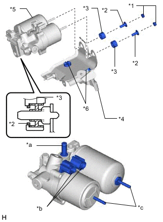
*1 Nut *2 Brake Actuator Case Collar *3 Brake Booster Pump Bushing *4 Brake Actuator Bracket Assembly *5 Brake Booster Pump Assembly *6 Brake Actuator Bracket Cushion *a Union *b Connector *c Stud Install the brake booster pump assembly, 2 brake booster pump bushings and 2 brake actuator case collars to the brake actuator bracket assembly with the 2 nuts.
- Torque:
- 5.4 N*m { 55 kgf*cm, 48 in.*lbf }
Note
-
When handling the brake booster pump assembly, do not hold it at the parts marked *a, *b and *c in the illustration.
-
Do not drop the brake booster pump assembly when carrying it. Do not use a brake booster pump assembly that has been dropped.
-
Do not damage the brake tubes and clamps. If they get damaged, replace with new ones.
-
Do not allow brake fluid to contact the inside of the connector.
-
When installing the brake booster pump assembly to the brake actuator bracket assembly, confirm that the 2 brake actuator bracket cushions are on the brake actuator bracket assembly, and brake booster pump bushing and brake booster pump collar are on the brake booster pump assembly.
-
Do not remove the hole plug before installing a new brake booster pump assembly because the brake booster pump assembly is filled with brake fluid.
-
-
INSTALL BRAKE BOOSTER PUMP ASSEMBLY WITH BRACKET
-
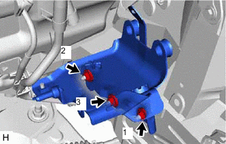
Install the brake booster pump assembly with bracket with the 3 nuts.
- Torque:
- 19 N*m { 194 kgf*cm, 14 ft.*lbf }
Note
Tighten the 3 nuts in the order shown in the illustration.
-
Attach the brake tube clamp to the brake actuator bracket assembly.
-
Attach the clamp to the brake booster pump bracket assembly.
-
Connect the 2 connectors to the brake booster pump assembly.
-
-
INSTALL NO. 1 BRAKE TUBE CLAMP BRACKET
-
Install the No. 1 brake tube clamp bracket to the brake booster pump assembly with the bolt.
- Torque:
- 5.0 N*m { 51 kgf*cm, 44 in.*lbf }
-
-
INSTALL FRONT NO. 1 BRAKE TUBE
-
Install the front No. 1 brake tube to the brake booster pump assembly with the bolt.
- Torque:
- 5.0 N*m { 51 kgf*cm, 44 in.*lbf }
-
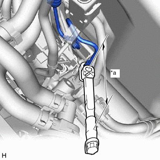
*a Torque Wrench Fulcrum Length Using a union nut wrench, connect the front No. 1 brake tube to the brake booster pump assembly to install it.
- Torque:
- Specified tightening torque
- 15.2 N*m { 155 kgf*cm, 11 ft.*lbf }
Tech Tips
-
Calculate the torque wrench reading when changing the fulcrum length of the torque wrench.
-
When using union nut wrench (fulcrum length of 22 mm (0.8661 in.)) + torque wrench (fulcrum length of 162 mm(6.3779 in.)): 13.4 N*m (137 kgf*cm,10 ft.*lbf)
-
-
CONNECT NO. 1 BRAKE ACTUATOR HOSE
-
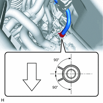

Front of Vehicle Connect the No. 1 brake actuator hose to the brake booster pump assembly with bracket and secure the hose with the clip.
Note
-
Connect the No. 1 brake actuator hose with the identification paint mark within 30° of the rib on the brake booster pump assembly with bracket.
-
Install the clip within the range shown in the illustration.
-
-
-
INSTALL HEATER ACCESSORY ASSEMBLY
-
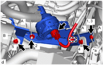
*a Temporary Bolt Temporarily install the heater water pump assembly (heater water pump) with the 3 bolts and nut.
-
Install the 3 bolts and nut in the order as shown in the illustration.
- Torque:
- for Bolt A, Nut A
- 9.8 N*m { 100 kgf*cm, 87 in.*lbf }
- for Bolt B
- 7.7 N*m { 79 kgf*cm, 68 in.*lbf }
-
Attach the clamp.
-
Connect the connector.
-
-
INSTALL BRAKE BOOSTER WITH MASTER CYLINDER ASSEMBLY (for LHD)
-
INSTALL AIR CLEANER CASE SUB-ASSEMBLY
-
FILL RESERVOIR WITH BRAKE FLUID
-
CONNECT CABLE TO NEGATIVE AUXILIARY BATTERY TERMINAL
-
INSTALL DECK FLOOR BOX LH (w/ Spare Tire)
-
INSTALL REAR DECK FLOOR BOX (w/ Spare Tire)
-
INSTALL NO. 3 DECK BOARD SUB-ASSEMBLY (w/ Spare Tire)
-
BLEED BRAKE SYSTEM