BRAKE BOOSTER(for RHD) INSTALLATION
PROCEDURE
-
INSTALL BRAKE BOOSTER GASKET
-
Install a new brake booster gasket to the brake booster with master cylinder assembly.
-
-
INSTALL BRAKE BOOSTER WITH MASTER CYLINDER ASSEMBLY
-
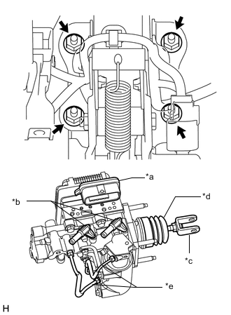
*a Connector Portion *b Union *c Push Rod Clevis *d Boot *e Front No. 2 Brake Tube Install the brake booster with master cylinder assembly with the 4 nuts.
- Torque:
- 12.7 N*m { 130 kgf*cm, 9 ft.*lbf }
Note
-
Do not kink or damage the brake tubes.
-
Do not carry the brake booster with master cylinder assembly by the portion shown in the illustration.
-
Be careful not to allow brake fluid to enter the connector of ECU.
-
If installing a new brake booster with master cylinder assembly, do not remove the hole plugs before connecting the brake lines because the brake booster with master cylinder is filled with brake fluid.
-
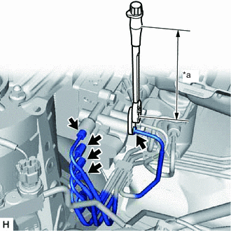
*a Torque Wrench Fulcrum Length Using the union nut wrench, connect each brake tube to the brake booster with master cylinder assembly.
- Torque:
- Specified tightening torque
- 15.2 N*m { 155 kgf*cm, 11 ft.*lbf }
Tech Tips
-
Calculate the torque wrench reading when changing the fulcrum length of the torque wrench.
-
When using union nut wrench (fulcrum length of 22 mm (0.8661 in.)) + torque wrench (fulcrum length of 162 mm(6.3779 in.)): 13.4 N*m (137 kgf*cm,10 ft.*lbf)
Note
Do not kink or damage the brake tube.
-
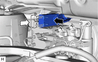

Connect the connector 
Lock the lock lever Connect the connector to the brake booster with master cylinder assembly.
Note
-
Make sure that the connector can be connected smoothly. Do not allow water, oil or dirt to enter.
-
Make sure that the connector lock is locked securely.
-
-
-
INSTALL PUSH ROD PIN
-
INSTALL RESERVOIR BRACKET
-
Install the reservoir bracket with the 2 bolts.
- Torque:
- 8.5 N*m { 87 kgf*cm, 75 in.*lbf }
-
-
CONNECT NO. 2 BRAKE ACTUATOR HOSE
-
Connect the No. 2 brake actuator hose to the No. 1 brake actuator tube, and slide the clip to secure it.
Note
-
When connecting the No. 2 brake actuator hose, connect it with the identification paint mark facing the front of the vehicle.
-
Make sure to install the hose to the proper location.
-
-
-
CONNECT NO. 1 RESERVOIR HOSE
-
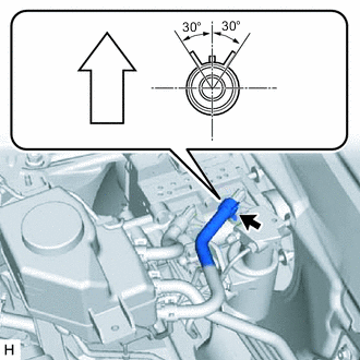
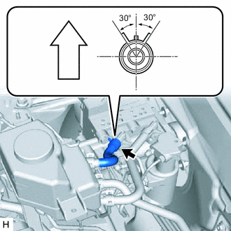
Up Connect the No. 1 reservoir hose to the brake booster with master cylinder assembly, and slide the clip to secure it.
Note
-
Connect the No. 1 eservoir hose with the identification paint mark within 30° of the rib of the brake booster with master cylinder assembly.
-
When connecting the No. 1 reservoir hose, face the identification mark up.
-
Make sure to install the hose to the proper location.
-
Install the clip within the range shown in the illustration.
-
-
-
CONNECT NO. 2 RESERVOIR HOSE
-
Up Connect the No. 2 reservoir hose to the brake booster with master cylinder assembly, and slide the clip to secure it.
Note
-
Connect the No. 2 reservoir hose with the identification paint mark within 30° of the rib of the brake booster with master cylinder assembly.
-
When connecting the No. 2 reservoir hose, face the identification mark up.
-
Make sure to install the hose to the proper location.
-
Install the clip within the range shown in the illustration.
-
-
-
BLEED NO. 1 BRAKE ACTUATOR TUBE
-
Add brake fluid into the brake master cylinder reservoir assembly.
-
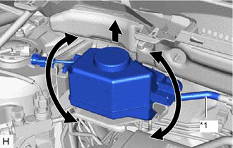
*1 No. 1 Brake Actuator Tube Lift up the brake master cylinder reservoir assembly as far as possible and rock it back and forth to bleed air from the No. 1 brake actuator tube.
Note
-
Do not damage the hoses.
-
Do not spill brake fluid.
-
Continue this procedure until only a minor amount of air remains in the brake actuator tube.
-
-
-
INSTALL BRAKE MASTER CYLINDER RESERVOIR ASSEMBLY
-
Install the brake master cylinder reservoir assembly to the reservoir bracket with the 2 bolts.
- Torque:
- 8.5 N*m { 87 kgf*cm, 75 in.*lbf }
-
Connect the reservoir level switch connector to the reservoir bracket.
-
-
INSTALL COWL BODY MOUNTING REINFORCEMENT RH
-
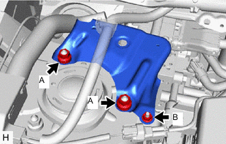
Install the cowl body mounting reinforcement RH with the 3 nuts.
- Torque:
- Nut (A)
- 50 N*m { 510 kgf*cm, 37 ft.*lbf }
- Nut (B)
- 8.5 N*m { 87 kgf*cm, 75 in.*lbf }
-
-
INSTALL OUTER COWL TOP PANEL
-
INSTALL SUSPENSION TOWER DAMPER (w/ Performance Rod)
-
INSTALL WINDSHIELD WIPER MOTOR AND LINK ASSEMBLY
-
FILL RESERVOIR WITH BRAKE FLUID
-
CONNECT CABLE TO NEGATIVE AUXILIARY BATTERY TERMINAL
-
BLEED BRAKE SYSTEM
-
INSPECT AND ADJUST BRAKE PEDAL
-
OBTAIN ZERO POINT OF YAW RATE AND ACCELERATION SENSOR
-
INSTALL NO. 1 INSTRUMENT PANEL UNDER COVER SUB-ASSEMBLY