BRAKE BOOSTER(for LHD) INSTALLATION
PROCEDURE
-
INSTALL BRAKE BOOSTER GASKET
-
Install a new brake booster gasket to the brake booster with master cylinder assembly.
-
-
INSTALL BRAKE BOOSTER WITH MASTER CYLINDER ASSEMBLY
-
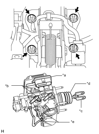
*a Connector Portion *b Union *c Push Rod Clevis *d Boot *e Front No. 2 Brake Tube Install the brake booster with master cylinder assembly with the 4 nuts.
- Torque:
- 12.7 N*m { 130 kgf*cm, 9 ft.*lbf }
Note
-
Do not kink or damage the brake tubes.
-
Do not carry the brake booster with master cylinder assembly by the portion shown in the illustration.
-
Be careful not to allow brake fluid to enter the connector of ECU.
-
If installing a new brake booster with master cylinder assembly, do not remove the hole plugs before connecting the brake lines because the brake booster with master cylinder is filled with brake fluid.
-
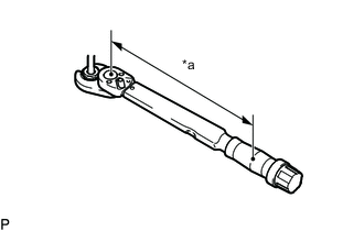
*a Torque Wrench Fulcrum Length Using a union nut wrench, tighten each brake line.
- Torque:
- Specified tightening torque
- 15.2 N*m { 155 kgf*cm, 11 ft.*lbf }
Note
Do not kink or damage the brake tubes.
Tech Tips
-
Calculate the torque wrench reading when changing the fulcrum length of the torque wrench.
-
When using union nut wrench (fulcrum length of 22 mm (0.8661 in.)) + torque wrench (fulcrum length of 162 mm(6.3779 in.)): 13.4 N*m (137 kgf*cm,10 ft.*lbf)
-
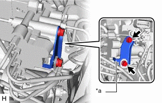
*a Stopper Install the No. 2 brake tube clamp bracket to the brake booster with master cylinder assembly with the 2 bolts.
- Torque:
- 5.0 N*m { 51 kgf*cm, 44 in.*lbf }
Note
Securely install the No. 2 brake tube clamp bracket so that its stopper contacts the brake booster with master cylinder assembly as shown in the illustration.
-
Connect the connector to the brake booster with master cylinder assembly.
Note
-
Make sure that the connector can be connected smoothly. Do not allow water, oil or dirt to enter.
-
Make sure that the connector lock is locked securely.
-
-
-
INSTALL RESERVOIR BRACKET
-
Install the reservoir bracket with the 2 bolts.
- Torque:
- 8.5 N*m { 87 kgf*cm, 75 in.*lbf }
-
-
CONNECT BRAKE ACTUATOR HOSE
-
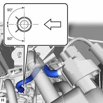

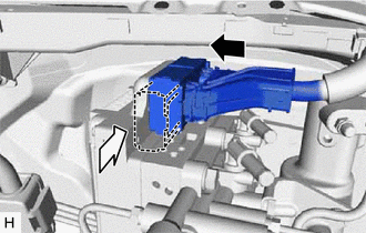
Vehicle Interior Connect the brake actuator hose to the brake booster pump assembly, and slide the clamp to secure it.
Note
-
Make sure to match the identification mark (green) on the hose with the brake booster pump rib.
-
Make sure to install the hose to the proper location.
-
Install the clip within the range shown in the illustration.
-
-
-
CONNECT NO. 1 RESERVOIR HOSE
-
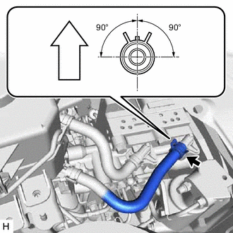
Up Connect the No. 1 reservoir hose to the brake booster with master cylinder assembly, and slide the clip to secure it.
Note
-
Make sure to match the identification mark (white (unpainted color)) on the hose and brake booster with master cylinder assembly.
-
When connecting the No. 1 reservoir hose, face the identification mark up.
-
Make sure to install the hose to the proper location.
-
Install the clip within the range shown in the illustration.
-
-
-
CONNECT NO. 2 RESERVOIR HOSE
-
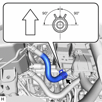
Up Connect the No. 2 reservoir hose to the brake booster with master cylinder assembly, and slide the clip to secure it.
Note
-
Make sure to match the identification mark (green) on the No. 2 reservoir hose and brake booster with master cylinder assembly.
-
When connecting the No. 2 reservoir hose, face the identification mark up.
-
Make sure to install the hose to the proper location.
-
Install the clip within the range shown in the illustration.
-
-
-
INSTALL BRAKE MASTER CYLINDER RESERVOIR ASSEMBLY
-
Install the brake master cylinder reservoir with bracket with the 3 bolts.
- Torque:
- 8.5 N*m { 87 kgf*cm, 75 in.*lbf }
-
-
INSTALL PUSH ROD PIN
-
INSTALL AIR CLEANER CASE SUB-ASSEMBLY
-
FILL RESERVOIR WITH BRAKE FLUID
-
INSTALL COWL BODY MOUNTING REINFORCEMENT LH
-
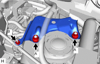
Install the cowl body mounting reinforcement LH with the 3 nuts.
- Torque:
- Nut A
- 50 N*m { 510 kgf*cm, 37 ft.*lbf }
- Nut B
- 8.5 N*m { 87 kgf*cm, 75 in.*lbf }
-
-
INSTALL OUTER COWL TOP PANEL
-
INSTALL SUSPENSION TOWER DAMPER
-
w/ Damper:
-
w/o Damper:
-
-
INSTALL WINDSHIELD WIPER MOTOR AND LINK ASSEMBLY
-
CONNECT CABLE TO NEGATIVE AUXILIARY BATTERY TERMINAL
-
BLEED BRAKE SYSTEM
-
INSPECT AND ADJUST BRAKE PEDAL
-
OBTAIN ZERO POINT OF YAW RATE AND ACCELERATION SENSOR
Tech Tips
After the brake booster with master cylinder assembly is replaced, obtain the zero point of the yaw rate and acceleration sensor.
-
INSTALL NO. 1 INSTRUMENT PANEL UNDER COVER SUB-ASSEMBLY