ELECTRONICALLY CONTROLLED BRAKE SYSTEM, Diagnostic DTC:C1381/97

| DTC Code | DTC Name |
|---|---|
| C1381/97 | Acceleration Sensor Power Supply Voltage Malfunction |
DESCRIPTION
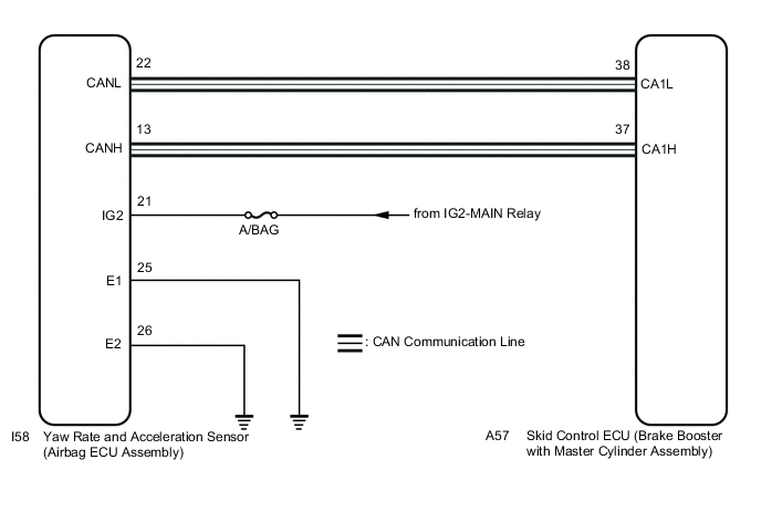
This DTC is stored when the skid control ECU (brake booster with master cylinder assembly) receives a sensor supply voltage malfunction signal from the yaw rate and acceleration sensor (airbag ECU assembly). This DTC may also be stored due to a temporary power source voltage drop.
| DTC No. | Detection Item | INF Code | DTC Detection Condition | Trouble Area | Note |
|---|---|---|---|---|---|
| C1381/97 | Acceleration Sensor Power Supply Voltage Malfunction | 601 | While acceleration sensor communication is enabled, a supply voltage malfunction signal is received from the sensor for 10 seconds. |
|
ABS DTC |
WIRING DIAGRAM
CAUTION / NOTICE / HINT
Note
-
When replacing the yaw rate and acceleration sensor (airbag ECU assembly), perform zero point calibration.
-
Inspect the fuses for circuits related to this system before performing the following inspection procedure.
PROCEDURE
-
CHECK HARNESS AND CONNECTOR (IG2 TERMINAL)
Note
-
After turning the power switch off, waiting time may be required before disconnecting the cable from the auxiliary battery terminal. Therefore, make sure to read the disconnecting the cable from the auxiliary battery terminal notice before proceeding with work.
-
When disconnecting the cable, some systems need to be initialized after the cable is reconnected.
-
Turn the power switch off.
-
Disconnect the cable from the negative (-) auxiliary battery terminal, and wait for at least 90 seconds.
-
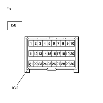
*a Front view of wire harness connector
(to Yaw Rate and Acceleration Sensor (Airbag ECU Assembly))
Make sure that there is no looseness at the locking part and the connecting part of the connector.
-
Disconnect the I58 yaw rate and acceleration sensor (airbag ECU assembly) connector.
-
Connect the cable to the negative (-) auxiliary battery terminal, and wait for at least 2 seconds.
-
Turn the power switch on (IG).
-
Operate all the components of the electrical system (defogger, wipers, headlights, heater blower, etc.).
-
Measure the voltage according to the value(s) in the table below.
Standard Voltage Tester Connection Switch Condition Specified Condition I58-21 (IG2) - Body ground Power switch on (IG) 11 to 14 V Result Proceed to OK NG
NG 
REPAIR OR REPLACE HARNESS OR CONNECTOR (IG CIRCUIT)
OK 
-
-
CHECK HARNESS AND CONNECTOR (E TERMINAL)
-
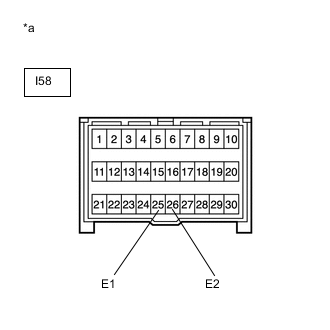
*a Front view of wire harness connector
(to Yaw Rate and Acceleration Sensor (Airbag ECU Assembly))
Turn the power switch off.
-
Measure the resistance according to the value(s) in the table below.
Standard Resistance Tester Connection Condition Specified Condition I58-25 (E1) - Body ground Always Below 1 Ω I58-26 (E2) - Body ground Always Below 1 Ω Tech Tips
If troubleshooting has been carried out according to Problem Symptoms Table, refer back to the table and proceed to the next step.
Result Proceed to OK NG
NG
REPAIR OR REPLACE HARNESS OR CONNECTOR (GND CIRCUIT)
OK
-
-
RECONFIRM DTC
-
Reconnect the I58 yaw rate and acceleration sensor (airbag ECU assembly) connector.
-
Clear the DTC.
Chassis > ABS/VSC/TRC > Clear DTCs -
Turn the power switch off.
-
Turn the power switch on (READY).
-
Perform a road test.
-
Check if the same DTC is recorded.
Chassis > ABS/VSC/TRC > Trouble CodesResult Result Proceed to DTC C1381/97 is not output A DTC C1381/97 is output B Tech Tips
If troubleshooting has been carried out according to Problem Symptoms Table, refer back to the table and proceed to the next step.
A
USE SIMULATION METHOD TO CHECK Click here
B
REPLACE AIRBAG ECU ASSEMBLY Click here
-