ELECTRONICALLY CONTROLLED BRAKE SYSTEM, Diagnostic DTC:C1273/73, C1274/74, C1466/33, C1467/34

| DTC Code | DTC Name |
|---|---|
| C1273/73 | Low Output Signal of Rear Speed Sensor RH (Test Mode DTC) |
| C1274/74 | Low Output Signal of Rear Speed Sensor LH (Test Mode DTC) |
| C1466/33 | Rear Speed Sensor RH Circuit |
| C1467/34 | Rear Speed Sensor LH Circuit |
DESCRIPTION
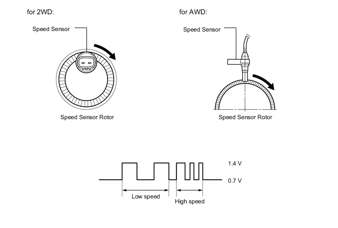
Each speed sensor detects the wheel speed and sends the signals to the skid control ECU (brake booster with master cylinder assembly). These signals are used for ABS control.
DTCs C1273/73 and C1274/74 are cleared when the speed sensor sends a wheel speed signal or when Test Mode ends. DTCs C1273/73 and C1274/74 are output only in Test Mode.
| DTC No. | Detection Item | INF Code | DTC Detection Condition | Trouble Area | Note |
|---|---|---|---|---|---|
| C1273/73 | Low Output Signal of Rear Speed Sensor RH (Test Mode DTC) | - | Detected only during Test Mode. |
|
ABS Test Mode DTC |
| C1274/74 | Low Output Signal of Rear Speed Sensor LH (Test Mode DTC) | - | Detected only during Test Mode. |
|
ABS Test Mode DTC |
| C1466/33 | Rear Speed Sensor RH Circuit | 521 522 523 524 526 527 528 |
|
|
ABS DTC |
| C1467/34 | Rear Speed Sensor LH Circuit | 531 532 533 534 536 537 538 |
|
|
ABS DTC |
Tech Tips
-
DTCs C1466/33 and C1273/73 are for the rear speed sensor RH.
-
DTCs C1467/34 and C1274/74 are for the rear speed sensor LH.
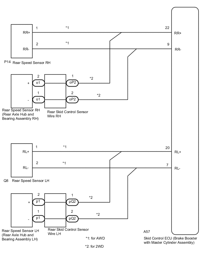
WIRING DIAGRAM
CAUTION / NOTICE / HINT
Note
When replacing the skid control ECU (brake booster with master cylinder assembly), perform initialization and calibration of the linear solenoid valve.
PROCEDURE
-
CHECK HARNESS AND CONNECTOR (MOMENTARY INTERRUPTION)
-
Using the GTS, check for any momentary interruptions in the wire harness and connector corresponding to a DTC.
Chassis > ABS/VSC/TRC > Data ListTester Display Measurement Item Range Normal Condition Diagnostic Note RR Speed Open Rear speed sensor RH open detection Error or Normal Normal: Normal Error: Momentary interruption RL Speed Open Rear speed sensor LH open detection Error or Normal Normal: Normal Error: Momentary interruption
Chassis > ABS/VSC/TRC > Data ListTester Display RR Speed Open RL Speed Open OK There are no momentary interruptions. Tech Tips
Perform the above inspection before removing the sensor and connector.
Result Proceed to OK NG (for AWD) NG (for 2WD)
NG (for AWD) 
GO TO STEP 5 Click here
NG (for 2WD)
GO TO STEP 14 Click here
OK 
-
-
READ VALUE USING GTS (REAR SPEED SENSOR)
-
Select the Data List on the GTS.
Chassis > ABS/VSC/TRC > Data ListTester Display Measurement Item Range Normal Condition Diagnostic Note RR Wheel Speed Rear speed sensor RH Min.: 0 km/h (0 mph), Max.: 326 km/h (202 mph) Vehicle stopped: 0 km/h (0 mph) When driving at constant speed: No large fluctuations RL Wheel Speed Rear speed sensor LH Min.: 0 km/h (0 mph), Max.: 326 km/h (202 mph) Vehicle stopped: 0 km/h (0 mph) When driving at constant speed: No large fluctuations
Chassis > ABS/VSC/TRC > Data ListTester Display RR Wheel Speed RL Wheel Speed -
Check the speed value output from the speed sensor displayed on the GTS.
Tech Tips
Factors that affect the indicated vehicle speed include tire size, tire inflation, and tire wear. The speed indicated on the speedometer has an allowable margin of error. This can be tested using a speedometer tester (calibrated chassis dynamometer). For details about testing and the margin of error, see the reference chart.
OK The speed value output from the speed sensor displayed on the GTS is similar to the speed indicated on the speedometer. Result Proceed to OK NG (for AWD) NG (for 2WD)
NG (for AWD)
GO TO STEP 5 Click here
NG (for 2WD)
GO TO STEP 14 Click here
OK
-
-
PERFORM TEST MODE INSPECTION (SIGNAL CHECK)
-
Turn the power switch off.
-
Perform the sensor check in Test Mode Procedure.
Chassis > ABS/VSC/TRC > UtilityTester Display Signal Check OK All Test Mode DTCs are cleared. Result Proceed to OK NG (for AWD) NG (for 2WD)
NG (for AWD)
CHECK REAR SPEED SENSOR INSTALLATION Click here
NG (for 2WD)
CHECK REAR SPEED SENSOR INSTALLATION Click here
OK
-
-
RECONFIRM DTC
-
Turn the power switch off.
-
Clear the DTCs.
Chassis > ABS/VSC/TRC > Clear DTCs -
Turn the power switch on (READY).
-
Perform a road test.
-
Check if the same DTC is output.
Chassis > ABS/VSC/TRC > Trouble CodesResult Result Proceed to DTCs C1466/33 and C1467/34 are not output. A DTCs C1466/33 and/or C1467/34 are output. (for AWD) B DTCs C1466/33 and/or C1467/34 are output. (for 2WD) C Tech Tips
If troubleshooting has been carried out according to Problem Symptoms Table, refer back to the table and proceed to the next step.
A 
USE SIMULATION METHOD TO CHECK Click here
B
GO TO STEP 10 Click here
C
GO TO STEP 19 Click here
-
-
CHECK REAR SPEED SENSOR INSTALLATION
-
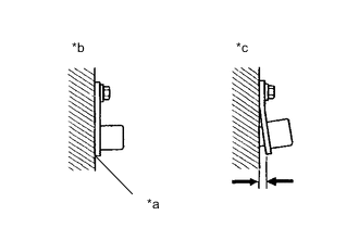
*a No clearance *b OK *c NG Turn the power switch off.
-
Check the speed sensor installation.
OK There is no clearance between the sensor and the rear axle carrier. The installation bolt is tightened properly. Result Proceed to OK NG
NG
INSTALL REAR SPEED SENSOR CORRECTLY Click here
OK
-
-
CHECK REAR SPEED SENSOR TIP
-
Remove the rear speed sensor.
-
Check the rear speed sensor tip.
OK The sensor tip is free of scratches, oil, and foreign matter. Note
-
If no damage to the speed sensor tip is found during this inspection, do not replace the speed sensor.
If there are any ferrous metal filings stuck to the rotor, this will result in a malfunction, so confirm that the rotor is not contaminated with foreign matter before replacing the sensor.
-
Check the speed sensor signal after cleaning or replacement.
Result Proceed to OK NG -
NG
CLEAN OR REPLACE REAR SPEED SENSOR
OK
-
-
CHECK HARNESS AND CONNECTOR (BRAKE BOOSTER WITH MASTER CYLINDER ASSEMBLY - REAR SPEED SENSOR)
-
Install the rear speed sensor.
-
Make sure that there is no looseness at the locking part and the connecting part of the connectors.
-
Disconnect the A57 skid control ECU (brake booster with master cylinder assembly) connector.
-
Disconnect the P14 or Q8 rear speed sensor connector.
-
Measure the resistance according to the value(s) in the table below.
Standard Resistance for RH Tester Connection Condition Specified Condition A57-22 (RR+) - P14-1 (RR+) Always Below 1 Ω A57-22 (RR+) or P14-1 (RR+) - Body ground Always 10 kΩ or higher A57-9 (RR-) - P14-2 (RR-) Always Below 1 Ω A57-9 (RR-) or P14-2 (RR-) - Body ground Always 10 kΩ or higher for LH Tester Connection Condition Specified Condition A57-20 (RL+) - Q8-1 (RL+) Always Below 1 Ω A57-20 (RL+) or Q8-1 (RL+) - Body ground Always 10 kΩ or higher A57-7 (RL-) - Q8-2 (RL-) Always Below 1 Ω A57-7 (RL-) or Q8-2 (RL-) - Body ground Always 10 kΩ or higher Result Proceed to OK NG
NG
REPAIR OR REPLACE HARNESS OR CONNECTOR
OK
-
-
INSPECT BRAKE BOOSTER WITH MASTER CYLINDER ASSEMBLY (SENSOR OUTPUT)
-
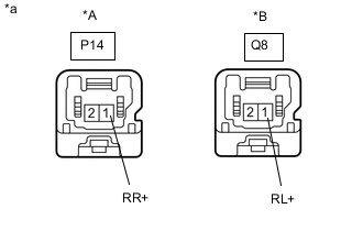
*A for RH *B for LH *a Front view of wire harness connector
(to Rear Speed Sensor)
Reconnect the A57 skid control ECU (brake booster with master cylinder assembly) connector.
-
Turn the power switch on (IG).
-
Measure the voltage according to the value(s) in the table below.
Standard Voltage for RH Tester Connection Switch Condition Specified Condition P14-1 (RR+) - Body ground Power switch on (IG) 5.7 to 14 V for LH Tester Connection Switch Condition Specified Condition Q8-1 (RL+) - Body ground Power switch on (IG) 5.7 to 14 V Result Proceed to OK NG
NG
REPLACE BRAKE BOOSTER WITH MASTER CYLINDER ASSEMBLY for LHD: Click here
REPLACE BRAKE BOOSTER WITH MASTER CYLINDER ASSEMBLY for RHD: Click hereOK
-
-
RECONFIRM DTC
-
Turn the power switch off.
-
Reconnect the P14 or Q8 rear speed sensor connector.
-
Clear the DTCs.
Chassis > ABS/VSC/TRC > Clear DTCs -
Turn the power switch on (READY).
-
Perform a road test.
-
Check if the same DTC is output.
Chassis > ABS/VSC/TRC > Trouble CodesResult Result Proceed to DTCs C1466/33 and/or C1467/34 are output. A DTCs C1466/33 and C1467/34 are not output. B Tech Tips
If troubleshooting has been carried out according to Problem Symptoms Table, refer back to the table and proceed to the next step.
B
USE SIMULATION METHOD TO CHECK Click here
A
-
-
REPLACE REAR SPEED SENSOR
-
Turn the power switch off.
-
Replace the rear speed sensor.
Result Proceed to NEXT
NEXT
-
-
RECONFIRM DTC
-
Clear the DTCs.
Chassis > ABS/VSC/TRC > Clear DTCs -
Turn the power switch on (READY).
-
Perform a road test.
-
Check if the same DTC is output.
Chassis > ABS/VSC/TRC > Trouble CodesResult Result Proceed to DTCs C1466/33 and/or C1467/34 are output. A DTCs C1466/33 and C1467/33 are not output. B Tech Tips
If troubleshooting has been carried out according to Problem Symptoms Table, refer back to the table and proceed to the next step.
B
END
A
-
-
REPLACE REAR AXLE HUB AND BEARING ASSEMBLY
-
Turn the power switch off.
-
Replace the rear speed sensor rotor (rear axle hub and bearing assembly).
Tech Tips
The rear speed sensor rotor is incorporated into the rear axle hub and bearing assembly.
If the rear speed sensor rotor needs to be replaced, replace the rear axle hub and bearing assembly.
Result Proceed to NEXT
NEXT
-
-
RECONFIRM DTC
-
Clear the DTCs.
Chassis > ABS/VSC/TRC > Clear DTCs -
Turn the power switch on (READY).
-
Perform a road test.
-
Check if the same DTC is output.
Chassis > ABS/VSC/TRC > Trouble CodesResult Result Proceed to DTCs C1466/33 and/or C1467/33 are output. A DTCs C1466/33 and C1467/34 are not output. B Tech Tips
If troubleshooting has been carried out according to Problem Symptoms Table, refer back to the table and proceed to the next step.
A
REPLACE BRAKE BOOSTER WITH MASTER CYLINDER ASSEMBLY for LHD: Click here
REPLACE BRAKE BOOSTER WITH MASTER CYLINDER ASSEMBLY for RHD: Click hereB
END
-
-
CHECK REAR SPEED SENSOR INSTALLATION
-
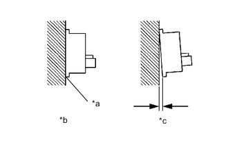
*a No clearance *b OK *c NG Turn the power switch off.
-
Check the speed sensor installation.
OK There is no clearance between the sensor and rear axle hub. Result Proceed to OK NG
NG
REPLACE REAR AXLE HUB AND BEARING ASSEMBLY Click here
OK
-
-
INSPECT REAR SKID CONTROL SENSOR WIRE
-
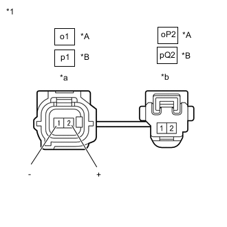
*A for RH *B for LH *1 Rear Skid Control Sensor Wire *a Front view of wire harness connector
(to Sensor Side Connector)
*b Front view of wire harness connector
(to Vehicle Side Connector)
Make sure that there is no looseness at the locking part and the connecting part of the connectors.
-
Disconnect the o1 or p1 rear skid control sensor wire connector.
-
Disconnect the oP2 or pQ2 rear skid control sensor wire connector.
-
Measure the resistance according to the value(s) in the table below.
Standard Resistance for RH Tester Connection Condition Specified Condition o1-2 (+) - oP2-1 Always Below 1 Ω o1-2 (+) or oP2-1 - Body ground and other terminals Always 10 kΩ or higher o1-1 (-) - oP2-2 Always Below 1 Ω o1-1 (-) or oP2-2 - Body ground and other terminals Always 10 kΩ or higher for LH Tester Connection Condition Specified Condition p1-2 (+) - pQ2-1 Always Below 1 Ω p1-2 (+) or pQ2-1 - Body ground and other terminals Always 10 kΩ or higher p1-1 (-) - pQ2-2 Always Below 1 Ω p1-1 (-) or pQ2-2 - Body ground and other terminals Always 10 kΩ or higher Result Proceed to OK NG
NG
REPLACE REAR SKID CONTROL SENSOR WIRE Click here
OK
-
-
CHECK HARNESS AND CONNECTOR (BRAKE BOOSTER WITH MASTER CYLINDER ASSEMBLY - REAR SPEED SENSOR)
-
Make sure that there is no looseness at the locking part and the connecting part of the connector.
-
Reconnect the oP2 or pQ2 rear skid control sensor wire connector.
-
Disconnect the A57 skid control ECU (brake booster with master cylinder assembly) connector.
-
Measure the resistance according to the value(s) in the table below.
Standard Resistance for RH Tester Connection Condition Specified Condition A57-22 (RR+) - o1-2 (+) Always Below 1 Ω A57-22 (RR+) or o1-2 (+) - Body ground Always 10 kΩ or higher A57-9 (RR-) - o1-1 (-) Always Below 1 Ω A57-9 (RR-) or o1-1 (-) - Body ground Always 10 kΩ or higher for LH Tester Connection Condition Specified Condition A57-20 (RL+) - p1-2 (+) Always Below 1 Ω A57-20 (RL+) or p1-2 (+) - Body ground Always 10 kΩ or higher A57-7 (RL-) - p1-1 (-) Always Below 1 Ω A57-7 (RL-) or p1-1 (-) - Body ground Always 10 kΩ or higher Result Proceed to OK NG
NG
REPAIR OR REPLACE HARNESS OR CONNECTOR
OK
-
-
INSPECT BRAKE BOOSTER WITH MASTER CYLINDER ASSEMBLY (SENSOR OUTPUT)
-
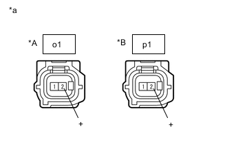
*A for RH *B for LH *a Front view of wire harness connector
(to Rear Speed Sensor)
Reconnect the A57 skid control ECU (brake booster with master cylinder assembly) connector.
-
Turn the power switch on (IG).
-
Measure the voltage according to the value(s) in the table below.
Standard Voltage for RH Tester Connection Condition Specified Condition o1-2 (+) - Body ground Power switch on (IG) 5.7 to 14 V for LH Tester Connection Condition Specified Condition p1-2 (+) - Body ground Power switch on (IG) 5.7 to 14 V Result Proceed to OK NG
NG
REPLACE BRAKE BOOSTER WITH MASTER CYLINDER ASSEMBLY for LHD: Click here
REPLACE BRAKE BOOSTER WITH MASTER CYLINDER ASSEMBLY for RHD: Click hereOK
-
-
RECONFIRM DTC
-
Turn the power switch off.
-
Reconnect the o1 or p1 rear skid control sensor wire connector.
-
Clear the DTCs.
Chassis > ABS/VSC/TRC > Clear DTCs -
Turn the power switch on (READY).
-
Perform a road test.
-
Check if the same DTC is output.
Chassis > ABS/VSC/TRC > Trouble CodesResult Result Proceed to DTCs C1466/33 and/or C1467/34 are output. A DTCs C1466/33 and C1467/34 are not output. B Tech Tips
If troubleshooting has been carried out according to Problem Symptoms Table, refer back to the table and proceed to the next step.
B
USE SIMULATION METHOD TO CHECK Click here
A
-
-
REPLACE REAR AXLE HUB AND BEARING ASSEMBLY
-
Turn the power switch off.
-
Replace the rear speed sensor rotor with rear speed sensor (rear axle hub and bearing assembly).
Tech Tips
The rear speed sensor rotor is incorporated into the rear axle hub and bearing assembly.
If the rear speed sensor rotor needs to be replaced, replace the rear axle hub and bearing assembly with rear speed sensor.
Result Proceed to NEXT
NEXT
-
-
RECONFIRM DTC
-
Clear the DTCs.
Chassis > ABS/VSC/TRC > Clear DTCs -
Turn the power switch on (READY).
-
Perform a road test.
-
Check if the same DTC is output.
Chassis > ABS/VSC/TRC > Trouble CodesResult Result Proceed to DTCs C1466/33 and/or C1467/34 are output. A DTCs C1466/33 and C1467/34 are not output. B Tech Tips
If troubleshooting has been carried out according to Problem Symptoms Table, refer back to the table and proceed to the next step.
A
REPLACE BRAKE BOOSTER WITH MASTER CYLINDER ASSEMBLY for LHD: Click here
REPLACE BRAKE BOOSTER WITH MASTER CYLINDER ASSEMBLY for RHD: Click hereB
END
-