TIRE PRESSURE WARNING SYSTEM TERMINALS OF ECU

-
CHECK TIRE PRESSURE WARNING ECU AND RECEIVER
-
Disconnect the P11*1 or Q46*2 tire pressure warning ECU and receiver connector and measure the voltage or resistance on the wire harness side.
-
*1: except AYZ10R-AWXLBQ or AYZ15R-AWXLBQ Deck Floor Box LH without Compact Spare Tire Caution Label
-
*2: for AYZ10R-AWXLBQ or AYZ15R-AWXLBQ Deck Floor Box LH without Compact Spare Tire Caution Label

*A except AYZ10R-AWXLBQ or AYZ15R-AWXLBQ Deck Floor Box LH without Compact Spare Tire Caution Label *B for AYZ10R-AWXLBQ or AYZ15R-AWXLBQ Deck Floor Box LH without Compact Spare Tire Caution Label *a Front view of wire harness connector
(to Tire Pressure Warning ECU and Receiver)
- - except AYZ10R-AWXLBQ or AYZ15R-AWXLBQ Deck Floor Box LH without Compact Spare Tire Caution Label Terminal No. (Symbol) Wiring Color Terminal Description Condition Specified Condition P11-1 (IG) - P11-12 (GND) GR - W-B*1
Y - W-B*2
IG power source Power switch on (IG) 10 to 16 V P11-7 (+B) - P11-12 (GND) L - W-B Power supply (from battery) Always 10 to 16 V P11-12 (GND) - Body ground W-B - Body ground Ground Always Below 1 Ω *1: for LHD
*2: for RHD
for AYZ10R-AWXLBQ or AYZ15R-AWXLBQ Deck Floor Box LH without Compact Spare Tire Caution Label Terminal No. (Symbol) Wiring Color Terminal Description Condition Specified Condition Q46-1 (IG) - Q46-12 (GND) P - W-B IG power source Power switch on (IG) 10 to 16 V Q46-12 (GND) - Body ground W-B - Body ground Ground Always Below 1 Ω -
-
Connect the P11*1 or Q46*2 tire pressure warning ECU and receiver connector.
-
*1: except AYZ10R-AWXLBQ or AYZ15R-AWXLBQ Deck Floor Box LH without Compact Spare Tire Caution Label
-
*2: for AYZ10R-AWXLBQ or AYZ15R-AWXLBQ Deck Floor Box LH without Compact Spare Tire Caution Label
-
-
Measure the voltage and resistance according to the value(s) in the table below. If the result is not as specified, the ECU may be malfunctioning.
Tech Tips
Measure the values on the wire harness side while the connector is connected.

*A except AYZ10R-AWXLBQ or AYZ15R-AWXLBQ Deck Floor Box LH without Compact Spare Tire Caution Label *B for AYZ10R-AWXLBQ or AYZ15R-AWXLBQ Deck Floor Box LH without Compact Spare Tire Caution Label *a Component with harness connected
(Tire Pressure Warning ECU and Receiver)
- - except AYZ10R-AWXLBQ or AYZ15R-AWXLBQ Deck Floor Box LH without Compact Spare Tire Caution Label Terminal No. (Symbol) Wiring Color Terminal Description Condition Specified Condition P11-3 (CLSW) - P11-12 (GND) LG - W-B*1
L - W-B*2
Tire pressure warning reset switch
-
Power switch on (IG)
-
"ENTER" switch (steering pad switch assembly) off
8 to 15 V
-
Power switch on (IG)
-
Steering pad switch assembly operated, "TPMS" selected on the multi-information display and "ENTER" switch (steering pad switch assembly) pressed and held
Below 1.5 V P11-4 (RDA) - P11-12 (GND) SB - W-B*1
P - W-B*2
Output signals Power switch on (IG) Pulse generation (see waveform 1) P11-5 (PRG) - P11-12 (GND) W - W-B Input signals Power switch on (IG) Pulse generation (see waveform 1) P11-8 (ALSI)*3 - P11-12 (GND) G - W-B Tire pressure monitor initiator driver Power switch on (IG) Pulse generation (see waveform 1) *1: for LHD
*2: for RHD
*3: w/ Tire Inflation Pressure Display Function
for AYZ10R-AWXLBQ or AYZ15R-AWXLBQ Deck Floor Box LH without Compact Spare Tire Caution Label Terminal No. (Symbol) Wiring Color Terminal Description Condition Specified Condition Q46-3 (CLSW) - Q46-12 (GND) B - W-B Tire pressure warning reset switch
-
Power switch on (IG)
-
"ENTER" switch (steering pad switch assembly) off
8 to 15 V
-
Power switch on (IG)
-
Steering pad switch assembly operated, "TPMS" selected on the multi-information display and "ENTER" switch (steering pad switch assembly) pressed and held
Below 1.5 V Q46-4 (RDA2) - Q46-12 (GND) V - W-B Output signals Power switch on (IG) Pulse generation (see waveform 1) Q46-5 (PRG2) - Q46-12 (GND) G - W-B Input signals Power switch on (IG) Pulse generation (see waveform 1) -
-
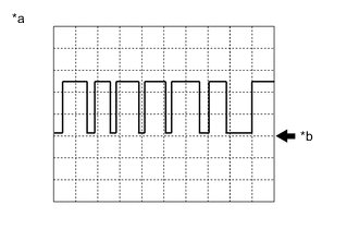
*a Example *b GND Using an oscilloscope, check waveform 1.
Waveform 1: Item Contents Terminal P11-4 (RDA) - P11-12 (GND)*1
P11-5 (PRG) - P11-12 (GND)*1
P11-8 (ALSI) - P11-12 (GND)*1, *3
Q46-4 (RDA2) - Q46-12 (GND)*2
Q46-5 (PRG2) - Q46-12 (GND)*2
Tool setting 5 V/DIV, 5 ms./DIV. Vehicle condition Power switch on (IG)
-
*1: except AYZ10R-AWXLBQ or AYZ15R-AWXLBQ Deck Floor Box LH without Compact Spare Tire Caution Label
-
*2: for AYZ10R-AWXLBQ or AYZ15R-AWXLBQ Deck Floor Box LH without Compact Spare Tire Caution Label
-
*3: w/ Tire Inflation Pressure Display Function
Tech Tips
The waveform shown in the illustration is an example. If the tester displays a waveform that alternates between high and low, where high is a voltage that is between the IG power source voltage and a voltage 2.2 V lower than the IG power source voltage, and where low is a voltage of between 0 and 1.2 V, the ECU can be judged normal.
-
-