REAR SUSPENSION MEMBER INSTALLATION

PROCEDURE
-
INSTALL CABLE SUPPORT BRACKET
-
Install the cable support bracket to the rear suspension member sub-assembly with the 2 bolts.
- Torque:
- 6.0 N*m { 61 kgf*cm, 53 in.*lbf }
-
-
INSTALL REAR STABILIZER SUPPORT BRACKET LH
-
Install the rear stabilizer support bracket LH to the rear suspension member sub-assembly with the 4 bolts.
- Torque:
- 50 N*m { 510 kgf*cm, 37 ft.*lbf }
-
-
INSTALL REAR STABILIZER SUPPORT BRACKET RH
-
Install the rear stabilizer support bracket RH to the rear suspension member sub-assembly with the 4 bolts.
- Torque:
- 50 N*m { 510 kgf*cm, 37 ft.*lbf }
-
-
INSTALL REAR STABILIZER BUSHING
-
INSTALL REAR STABILIZER BAR
-
INSTALL REAR NO. 1 STABILIZER BAR BRACKET
-
INSTALL FRONT DIFFERENTIAL SUPPORT ASSEMBLY (for AWD)
-
INSTALL DIFFERENTIAL MOUNT CUSHION (for AWD)
-
INSTALL REAR TRACTION WITH TRANSAXLE MOTOR ASSEMBLY (for AWD)
-
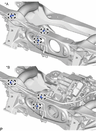
INSTALL REAR SUSPENSION MEMBER SUB-ASSEMBLY
-
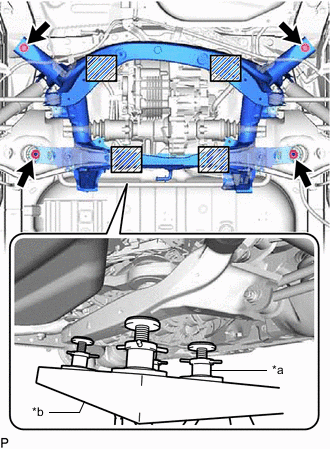
*a Plate Lift Attachment *b Engine Lifter 
Attachment Placement Positions Place wooden blocks or plate lift attachments on an engine lifter, and then set the rear suspension member sub-assembly so that the attachments are in the positions shown in the illustration.
Note
-
Place the wooden blocks or plate lift attachments so that the rear suspension member sub-assembly is level.
-
As the rear suspension member sub-assembly is very heavy, be sure to support it securely.
-
-
Install the rear suspension member and 2 rear upper body mounting cushions with the 2 bolts and 2 nuts.
- Torque:
- for bolt
- 102 N*m { 1040 kgf*cm, 75 ft.*lbf }
- for nut
- 125 N*m { 1275 kgf*cm, 92 ft.*lbf }
-
-
CONNECT WIRE HARNESS
-
*A for 2WD *B for AWD Attach the 3 clamps and connect the wire harness.
-
-
INSTALL EXHAUST TAILPIPE ASSEMBLY
-
TEMPORARILY INSTALL REAR NO. 2 SUSPENSION ARM ASSEMBLY LH
-
TEMPORARILY INSTALL REAR NO. 2 SUSPENSION ARM ASSEMBLY RH
Tech Tips
Use the same procedure described for the LH side.
-
TEMPORARILY INSTALL REAR NO. 1 SUSPENSION ARM ASSEMBLY LH
-
TEMPORARILY INSTALL REAR NO. 1 SUSPENSION ARM ASSEMBLY RH
Tech Tips
Use the same procedure described for the LH side.
-
TEMPORARILY INSTALL REAR UPPER CONTROL ARM ASSEMBLY LH
-
TEMPORARILY INSTALL REAR UPPER CONTROL ARM ASSEMBLY RH
Tech Tips
Use the same procedure described for the LH side.
-
TEMPORARILY INSTALL REAR SHOCK ABSORBER ASSEMBLY LH
-
TEMPORARILY INSTALL REAR SHOCK ABSORBER ASSEMBLY RH
Tech Tips
Use the same procedure described for the LH side.
-
INSTALL REAR AXLE CARRIER SUB-ASSEMBLY LH
-
INSTALL REAR AXLE CARRIER SUB-ASSEMBLY RH
Tech Tips
Use the same procedure described for the LH side.
-
TEMPORARILY INSTALL REAR NO. 2 SUSPENSION ARM ASSEMBLY LH
-
TEMPORARILY INSTALL REAR NO. 2 SUSPENSION ARM ASSEMBLY RH
Tech Tips
Use the same procedure described for the LH side.
-
INSTALL REAR TRAILING ARM ASSEMBLY LH
-
INSTALL REAR TRAILING ARM ASSEMBLY RH
Tech Tips
Use the same procedure described for the LH side.
-
TEMPORARILY INSTALL REAR NO. 1 SUSPENSION ARM ASSEMBLY LH
-
TEMPORARILY INSTALL REAR NO. 1 SUSPENSION ARM ASSEMBLY RH
Tech Tips
Use the same procedure described for the LH side.
-
CONNECT REAR NO. 1 SHOCK ABSORBER BRACKET LH
-
CONNECT REAR NO. 1 SHOCK ABSORBER BRACKET RH
Tech Tips
Use the same procedure described for the LH side.
-
INSTALL REAR HEIGHT CONTROL SENSOR SUB-ASSEMBLY LH
-
STABILIZE SUSPENSION
-
TIGHTEN REAR UPPER CONTROL ARM ASSEMBLY LH
-
TIGHTEN REAR UPPER CONTROL ARM ASSEMBLY RH
Tech Tips
Use the same procedure described for the LH side.
-
TIGHTEN REAR NO. 2 SUSPENSION ARM ASSEMBLY LH
-
TIGHTEN REAR NO. 2 SUSPENSION ARM ASSEMBLY RH
Tech Tips
Use the same procedure described for the LH side.
-
TIGHTEN REAR NO. 1 SUSPENSION ARM ASSEMBLY LH
-
TIGHTEN REAR NO. 1 SUSPENSION ARM ASSEMBLY RH
Tech Tips
Use the same procedure described for the LH side.
-
TIGHTEN REAR SHOCK ABSORBER ASSEMBLY LH
-
TIGHTEN REAR SHOCK ABSORBER ASSEMBLY RH
Tech Tips
Use the same procedure described for the LH side.
-
INSTALL REAR DISC BRAKE DUST COVER SUB-ASSEMBLY LH
-
INSTALL REAR DISC BRAKE DUST COVER SUB-ASSEMBLY RH
Tech Tips
Use the same procedure described for the LH side.
-
CONNECT PARKING BRAKE WIRE ASSEMBLY NO.1
-
INSTALL REAR SUSPENSION BRACE SUB-ASSEMBLY
-
Install the rear suspension brace sub-assembly to the rear suspension member with the 6 bolts.
- Torque:
- 35 N*m { 357 kgf*cm, 26 ft.*lbf }
-
-
INSTALL REAR STABILIZER LINK ASSEMBLY LH
-
INSTALL REAR STABILIZER LINK ASSEMBLY RH
Tech Tips
Use the same procedure described for the LH side.
-
INSTALL REAR AXLE HUB AND BEARING ASSEMBLY LH (for 2WD)
-
INSTALL REAR AXLE HUB AND BEARING ASSEMBLY RH (for 2WD)
Tech Tips
Use the same procedure described for the LH side.
-
INSTALL REAR AXLE HUB AND BEARING ASSEMBLY LH (for AWD)
-
INSTALL REAR AXLE HUB AND BEARING ASSEMBLY RH (for AWD)
Tech Tips
Use the same procedure described for the LH side.
-
INSTALL REAR DISC
-
CONNECT REAR DISC BRAKE CALIPER ASSEMBLY LH
-
CONNECT REAR DISC BRAKE CALIPER ASSEMBLY RH
Tech Tips
Use the same procedure described for the LH side.
-
INSTALL REAR AXLE SHAFT NUT LH (for AWD)
-
INSTALL REAR AXLE SHAFT NUT RH (for AWD)
Tech Tips
Use the same procedure described for the LH side.
-
INSPECT REAR AXLE HUB BEARING LOOSENESS
-
INSPECT REAR AXLE HUB RUNOUT
-
STAKE REAR AXLE SHAFT NUT LH (for AWD)
-
STAKE REAR AXLE SHAFT NUT RH (for AWD)
Tech Tips
Use the same procedure described for the LH side.
-
CONNECT REAR SKID CONTROL SENSOR WIRE LH (for 2WD)
-
w/o AVS:
-
w/ AVS:
-
-
CONNECT REAR SKID CONTROL SENSOR WIRE RH (for 2WD)
Tech Tips
Use the same procedure described for the LH side.
-
CONNECT REAR SPEED SENSOR LH (for AWD)
-
w/o AVS:
-
w/ AVS:
-
-
CONNECT REAR SPEED SENSOR RH (for AWD)
Tech Tips
Use the same procedure described for the LH side.
-
INSTALL REAR SUSPENSION ARM COVER LH
-
INSTALL REAR SUSPENSION ARM COVER RH
Tech Tips
Use the same procedure described for the LH side.
-
CONNECT WIRE HARNESS (for AWD)
-
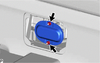
INSTALL SERVICE PLUG GRIP (for AWD)
CAUTION:
Wear insulating gloves.
Note
Before connecting the service plug, check that no parts and tools remain and that the high voltage terminals and connectors are connected securely.
-
Wear insulated gloves and install the service plug grip in the order shown in the illustration.
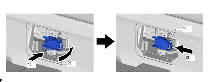
*1 Service Plug Grip Lever - -
-
Insert the service plug grip straight.
-
Push down the lever 90°.
-
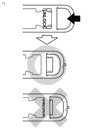
*1 Service Plug Grip Slide the lever until it clicks to indicate that it is locked.
Note
Slide firmly to the left until the UNLOCK indication is hidden.
-
-
Rotate the handle of the service plug grip 90° toward the battery and slide it in the direction shown by the arrow until a click sound is heard.
-
-
INSTALL HYBRID BATTERY SERVICE PLUG COVER (for AWD)
CAUTION:
Wear insulated gloves and use insulated tools.
-
Using an insulated tool, install the hybrid battery service plug cover with the 2 nuts.
-
-
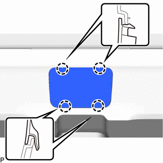
INSTALL BATTERY SERVICE HOLE COVER (for AWD)
-
Engage the 4 claws and install the battery service hole cover.
-
-
CONNECT CABLE TO NEGATIVE AUXILIARY BATTERY TERMINAL (for AWD)
-
Connect the cable to the negative (-) auxiliary battery terminal and tighten the nut.
- Torque:
- 5.4 N*m { 55 kgf*cm, 48 in.*lbf }
-
w/o Spare Tire:
Install the battery service cover and attach the 2 claws.
-
-
INSTALL DECK FLOOR BOX LH (for AWD w/ Spare Tire)
-
INSTALL REAR DECK FLOOR BOX (for AWD w/ Spare Tire)
-
INSTALL NO. 3 DECK BOARD SUB-ASSEMBLY (for AWD w/ Spare Tire)
-
INSTALL REAR WHEEL
-
INSPECT AND ADJUST REAR WHEEL ALIGNMENT
-
CHECK FOR SPEED SENSOR SIGNAL
-
HEIGHT CONTROL SENSOR SIGNAL INITIALIZATION
-
PERFORM INITIALIZATION