REAR SUSPENSION MEMBER REMOVAL

CAUTION / NOTICE / HINT
Note
-
When the brake pedal is first depressed after replacing the brake pads or pushing back the disc brake piston, DTC C1214 may be output. As there is no malfunction, clear the DTC.
-
While the auxiliary battery is connected, even if the power switch is off, the brake control system activates when the brake pedal is depressed or the door courtesy switch is turned on. Therefore, even if only brake shoes are to be removed and installed, be sure to perform the Disable Brake Control procedure and disconnect the cable from the negative (-) terminal of the auxiliary battery before beginning work.
Tech Tips
-
Use the same procedure for the RH and LH sides.
-
The procedure listed below is for the LH side.
PROCEDURE
-
PRECAUTION
Note
After turning the power switch off, waiting time may be required before disconnecting the cable from the negative (-) auxiliary battery terminal. Therefore, make sure to read the disconnecting the cable from the negative (-) auxiliary battery terminal notice before proceeding with work.
-
DISABLE BRAKE CONTROL
-
REMOVE REAR WHEEL
-
REMOVE NO. 3 DECK BOARD SUB-ASSEMBLY (for AWD w/ Spare Tire)
-
REMOVE REAR DECK FLOOR BOX (for AWD w/ Spare Tire)
-
REMOVE DECK FLOOR BOX LH (for AWD w/ Spare Tire)
-
DISCONNECT CABLE FROM NEGATIVE AUXILIARY BATTERY TERMINAL (for AWD)
-
w/o Spare Tire:
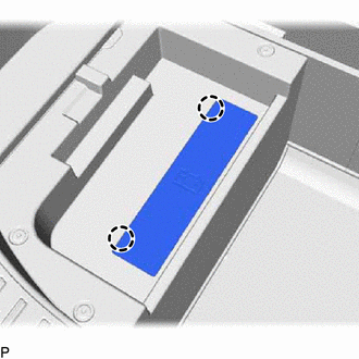
Detach the 2 claws and remove the battery service cover.
-
Loosen the nut and disconnect the cable from the negative (-) auxiliary battery terminal.
-
-
REMOVE BATTERY SERVICE HOLE COVER (for AWD)
-
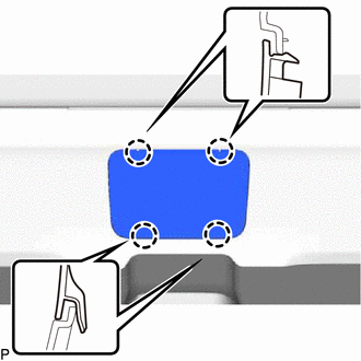
Disengage the 4 claws and remove the battery service hole cover.
Tech Tips
Disengage the upper 2 claws and then pull them up to remove.
-
-
REMOVE HYBRID BATTERY SERVICE PLUG COVER (for AWD)
CAUTION:
Wear insulated gloves and use insulated tools.
-
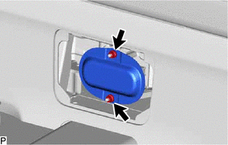
Using an insulated tool, remove the 2 nuts and hybrid battery service plug cover.
-
-
REMOVE SERVICE PLUG GRIP (for AWD)
CAUTION:
-
Be sure to wear insulated gloves.
-
Remove the service plug grip to interrupt the high voltage circuit at the time of inspection or repair.
-
Keep the removed service plug grip in your pocket to prevent other technicians from accidentally reconnecting it while you are servicing the vehicle.
-
All the high voltage wiring connectors are orange.
Note
After removing the service plug grip, turning the power switch on (READY) may cause a malfunction. Do not turn the power switch on (READY) unless instructed by the repair manual.
Tech Tips
Waiting for at least 10 minutes is required to discharge the high voltage capacitor inside the inverter with converter assembly.
-
Wear insulated gloves and remove the service plug grip after sliding up the lever of the service plug grip as shown in the illustration.
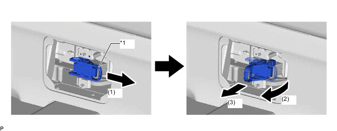
*1 Service Plug Grip Lever - -
-
Slide the lever to release the lock.
-
Lift the lever straight up.
Note
Do not exert excessive force to lift up the lever.
-
Draw the service plug grip out from the HV battery to remove it.
-
-
-
DISCONNECT WIRE HARNESS (for AWD)
-
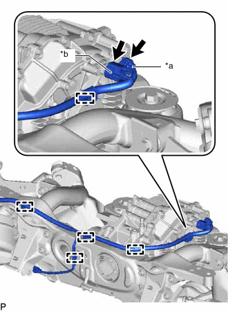
*a Temperature Sensor Connector *b Resolver Sensor Connector Disconnect the temperature sensor connector.
-
Disconnect the resolver sensor connector.
-
Disengage the 5 clamps.
-
Remove the 2 nuts and disconnect the No. 2 frame wire from the rear traction motor with transaxle assembly and vehicle body.
-
-
REMOVE REAR SUSPENSION ARM COVER LH
-
REMOVE REAR SUSPENSION ARM COVER RH
Tech Tips
Use the same procedure described for the LH side.
-
REMOVE REAR AXLE SHAFT NUT LH (for AWD)
-
REMOVE REAR AXLE SHAFT NUT RH (for AWD)
Tech Tips
Use the same procedure described for the LH side.
-
DISCONNECT REAR SKID CONTROL SENSOR WIRE LH (for 2WD)
-
w/o AVS:
-
w/ AVS:
-
-
DISCONNECT REAR SKID CONTROL SENSOR WIRE RH (for 2WD)
Tech Tips
Use the same procedure described for the LH side.
-
DISCONNECT REAR SPEED SENSOR LH (for AWD)
-
w/o AVS:
-
w/ AVS:
-
-
DISCONNECT REAR SPEED SENSOR RH (for AWD)
Tech Tips
Use the same procedure described for the LH side.
-
DISCONNECT REAR DISC BRAKE CALIPER ASSEMBLY LH
-
DISCONNECT REAR DISC BRAKE CALIPER ASSEMBLY RH
Tech Tips
Use the same procedure described for the LH side.
-
REMOVE REAR DISC
-
REMOVE REAR AXLE HUB AND BEARING ASSEMBLY LH (for 2WD)
-
REMOVE REAR AXLE HUB AND BEARING ASSEMBLY RH (for 2WD)
Tech Tips
Use the same procedure described for the LH side.
-
REMOVE REAR AXLE HUB AND BEARING ASSEMBLY LH (for AWD)
-
REMOVE REAR AXLE HUB AND BEARING ASSEMBLY RH (for AWD)
Tech Tips
Use the same procedure described for the LH side.
-
REMOVE REAR STABILIZER LINK ASSEMBLY LH
-
REMOVE REAR STABILIZER LINK ASSEMBLY RH
Tech Tips
Use the same procedure described for the LH side.
-
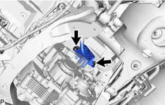
REMOVE REAR SUSPENSION BRACE SUB-ASSEMBLY
-
Remove the 6 bolts and rear suspension brace sub-assembly.
-
-
DISCONNECT PARKING BRAKE WIRE ASSEMBLY NO.1
-
REMOVE REAR DISC BRAKE DUST COVER SUB-ASSEMBLY LH
-
REMOVE REAR DISC BRAKE DUST COVER SUB-ASSEMBLY RH
Tech Tips
Use the same procedure described for the LH side.
-
REMOVE REAR HEIGHT CONTROL SENSOR SUB-ASSEMBLY LH
-
DISCONNECT REAR NO. 1 SHOCK ABSORBER BRACKET LH
-
DISCONNECT REAR NO. 1 SHOCK ABSORBER BRACKET RH
Tech Tips
Use the same procedure described for the LH side.
-
DISCONNECT REAR NO. 1 SUSPENSION ARM ASSEMBLY LH
-
DISCONNECT REAR NO. 1 SUSPENSION ARM ASSEMBLY RH
Tech Tips
Use the same procedure described for the LH side.
-
DISCONNECT REAR TRAILING ARM ASSEMBLY LH
-
DISCONNECT REAR TRAILING ARM ASSEMBLY RH
Tech Tips
Use the same procedure described for the LH side.
-
DISCONNECT REAR NO. 2 SUSPENSION ARM ASSEMBLY LH
-
DISCONNECT REAR NO. 2 SUSPENSION ARM ASSEMBLY RH
Tech Tips
Use the same procedure described for the LH side.
-
REMOVE REAR AXLE CARRIER SUB-ASSEMBLY LH
-
REMOVE REAR AXLE CARRIER SUB-ASSEMBLY RH
Tech Tips
Use the same procedure described for the LH side.
-
REMOVE REAR SHOCK ABSORBER ASSEMBLY LH
-
REMOVE REAR SHOCK ABSORBER ASSEMBLY RH
Tech Tips
Use the same procedure described for the LH side.
-
REMOVE REAR UPPER CONTROL ARM ASSEMBLY LH
-
REMOVE REAR UPPER CONTROL ARM ASSEMBLY RH
Tech Tips
Use the same procedure described for the LH side.
-
REMOVE REAR NO. 1 SUSPENSION ARM ASSEMBLY LH
-
REMOVE REAR NO. 1 SUSPENSION ARM ASSEMBLY RH
Tech Tips
Use the same procedure described for the LH side.
-
REMOVE REAR NO. 2 SUSPENSION ARM ASSEMBLY LH
-
REMOVE REAR NO. 2 SUSPENSION ARM ASSEMBLY RH
Tech Tips
Use the same procedure described for the LH side.
-
REMOVE EXHAUST TAILPIPE ASSEMBLY
-
DISCONNECT WIRE HARNESS
-
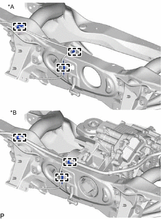
*A for 2WD *B for AWD Detach the 3 clamps and disconnect the wire harness.
-
-
REMOVE REAR SUSPENSION MEMBER SUB-ASSEMBLY
-
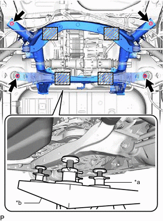
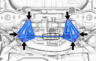
*a Plate Lift Attachment *b Engine Lifter 
Attachment Placement Positions Place wooden blocks or plate lift attachments in the positions shown in the illustration and set an engine lifter underneath the suspension member.
Note
-
Place the wooden blocks or plate lift attachments so that the rear suspension member sub-assembly is level.
-
As the rear suspension member sub-assembly is very heavy, be sure to support it securely.
-
-
Remove the 2 bolts, 2 nuts, 2 rear upper body mounting cushions and rear suspension member sub-assembly.
-
-
REMOVE REAR TRACTION WITH TRANSAXLE MOTOR ASSEMBLY (for AWD)
-
REMOVE DIFFERENTIAL MOUNT CUSHION (for AWD)
-
REMOVE FRONT DIFFERENTIAL SUPPORT ASSEMBLY (for AWD)
-
REMOVE REAR NO. 1 STABILIZER BAR BRACKET
-
REMOVE REAR STABILIZER BAR
-
REMOVE REAR STABILIZER BUSHING
-
REMOVE REAR STABILIZER SUPPORT BRACKET LH
-
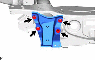
Remove the 4 bolts and rear stabilizer support bracket LH from the rear suspension member sub-assembly.
-
-
REMOVE REAR STABILIZER SUPPORT BRACKET RH
-
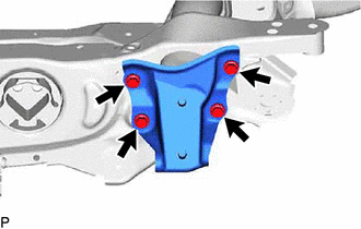
Remove the 4 bolts and rear stabilizer support bracket RH from the rear suspension member sub-assembly.
-
-
REMOVE CABLE SUPPORT BRACKET
-
Remove the 2 bolts and cable support bracket from the rear suspension member sub-assembly.
-