REAR LOWER ARM REMOVAL

CAUTION / NOTICE / HINT
Tech Tips
-
Use the same procedure for the RH and LH sides.
-
The procedure listed below is for the LH side.
PROCEDURE
-
REMOVE REAR WHEEL
-
REMOVE REAR SUSPENSION ARM COVER LH
-
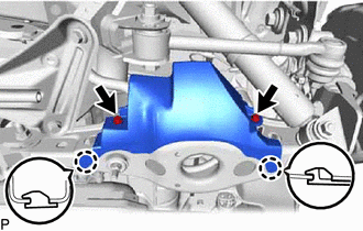
Remove the 2 bolts and disengage the 2 claws to remove the rear suspension arm cover LH from the rear No. 2 suspension arm assembly LH.
-
-
REMOVE REAR HEIGHT CONTROL SENSOR SUB-ASSEMBLY LH
-
REMOVE REAR SHOCK ABSORBER ASSEMBLY LH
-
REMOVE REAR NO. 1 SUSPENSION ARM ASSEMBLY LH
-
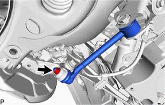
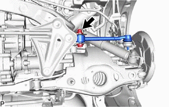
Remove the nut from the rear axle carrier.
-
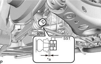
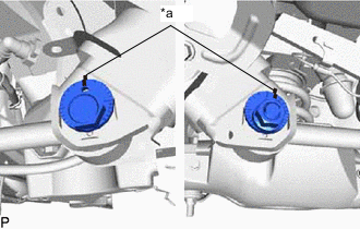
*a 1 mm (0.0394 in.) Install SST to the rear No. 1 suspension arm as shown in the illustration.
- SST
- 09960-20010 ( 09961-02060 )
Note
Make sure that the clearance measurement between SST and the rear axle assembly is 1 mm (0.0394 in.).
Tech Tips
Use 2 SST of the same type.
-
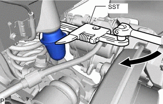
Using SST, disconnect the rear No. 1 suspension arm from the rear axle carrier as shown in the illustration.
- SST
- 09960-20010 ( 09961-02010 )
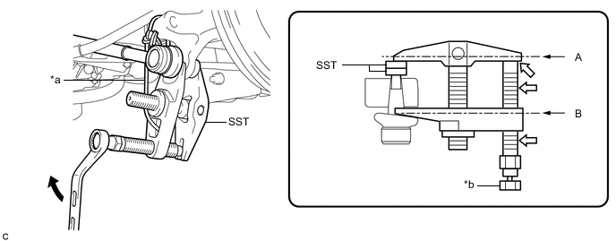
*a Tie the string so there is no slack *b Place the wrench here 
Turn 
Molybdenum grease CAUTION:
Apply molybdenum grease to the threads and end of SST bolt.
Note
-
Install SST so that A and B are parallel.
-
Be sure to turn the part indicated in the illustration with a wrench.
-
Do not damage the front lower ball joint dust cover.
-
Be sure to tie the string of SST to the vehicle to prevent SST from dropping.
-
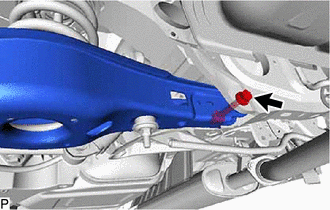
*a Matchmark Put matchmarks on the rear suspension toe adjust cam, No. 2 camber adjust cam and rear suspension member.
-
Remove the nut, No. 2 camber adjust cam, rear suspension toe adjust cam and rear No. 1 suspension arm assembly LH.
-
-
REMOVE REAR STABILIZER LINK ASSEMBLY LH
-
LOOSEN REAR NO. 2 SUSPENSION ARM ASSEMBLY LH
-
REMOVE REAR COIL SPRING LH
-
REMOVE REAR UPPER COIL SPRING INSULATOR LH
-
REMOVE REAR LOWER COIL SPRING INSULATOR LH
-
REMOVE REAR NO. 2 SUSPENSION ARM ASSEMBLY LH
-
Remove the bolt, nut and rear No. 2 suspension arm from the suspension member.
Note
Since a stopper nut is used, loosen the bolt.
-
-
REMOVE REAR NO. 1 SPRING BUMPER LH
-
Using SST, remove the rear No. 1 spring bumper LH.
- SST
- 09922-10010
-