FRONT LOWER SUSPENSION ARM INSTALLATION

CAUTION / NOTICE / HINT
Tech Tips
-
Use the same procedure for the RH and LH sides.
-
The procedure listed below is for the LH side.
PROCEDURE
-
TEMPORARILY INSTALL FRONT LOWER NO. 1 SUSPENSION ARM SUB-ASSEMBLY LH
-
Temporarily install the front lower No. 1 suspension arm sub-assembly LH to the front suspension crossmember sub-assembly with the 2 bolts and nut.
Note
Because the nut has its own stopper, do not turn the nut. Tighten the bolt with the nut fixed in place.
-
-
INSTALL FRONT SUSPENSION CROSSMEMBER SUB-ASSEMBLY
-
INSTALL FRONT WHEELS
-
STABILIZE SUSPENSION
-
Lower the vehicle.
-
Bounce the vehicle up and down at the corners several times to stabilize the suspension.
-
-
TIGHTEN FRONT LOWER NO. 1 SUSPENSION ARM SUB-ASSEMBLY LH
-
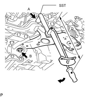
*a Torque Wrench Fulcrum Length 
Turn Using SST, tighten bolt A.
- SST
- 09961-01270
- Torque:
- Specified tightening torque
- 233 N*m { 2376 kgf*cm, 172 ft.*lbf }
Tech Tips
-
Calculate the torque wrench reading when changing the fulcrum length of the torque wrench.
-
When using SST (fulcrum length of 200 mm (7.8740 in.)) + torque wrench (fulcrum length of 1055 mm (41.5354 in.)): 195.9 N*m (1998 kgf*cm, 144 ft.*lbf)
-
Tighten bolt B.
- Torque:
- 214 N*m { 2182 kgf*cm, 158 ft.*lbf }
Note
Since a stopper nut is used, tighten the bolt.
-
-
INSPECT AND ADJUST FRONT WHEEL ALIGNMENT