ADAPTIVE VARIABLE SUSPENSION SYSTEM, Diagnostic DTC:C1731, C1732, C1733, C1734
| DTC Code | DTC Name |
|---|---|
| C1731 | Front Damping Force Control Actuator RH Circuit Malfunction |
| C1732 | Front Damping Force Control Actuator LH Circuit Malfunction |
| C1733 | Rear Damping Force Control Actuator RH Circuit Malfunction |
| C1734 | Rear Damping Force Control Actuator LH Circuit Malfunction |
DESCRIPTION
The absorber control actuator changes the damping force depending on absorber control ECU signals.
| DTC No. | Detection Item | DTC Detection Condition | Trouble Area | Warning Indicate |
|---|---|---|---|---|
| C1731 | Front Damping Force Control Actuator RH Circuit Malfunction | Either condition is met:
|
|
Does not come on |
| C1732 | Front Damping Force Control Actuator LH Circuit Malfunction | Either condition is met:
|
|
Does not come on |
| C1733 | Rear Damping Force Control Actuator RH Circuit Malfunction | Either condition is met:
|
|
Does not come on |
| C1734 | Rear Damping Force Control Actuator LH Circuit Malfunction | Either condition is met:
|
|
Does not come on |
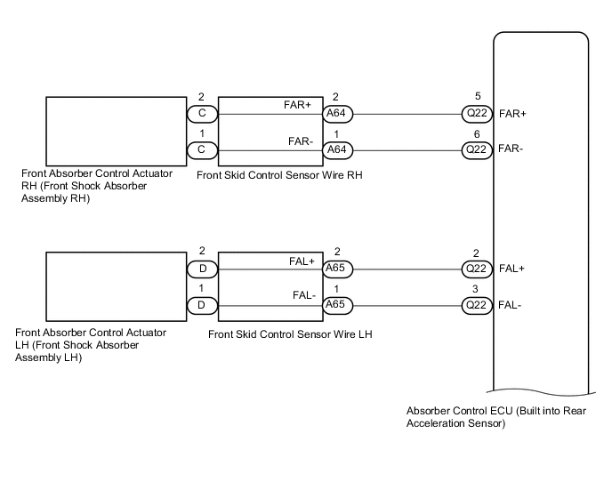
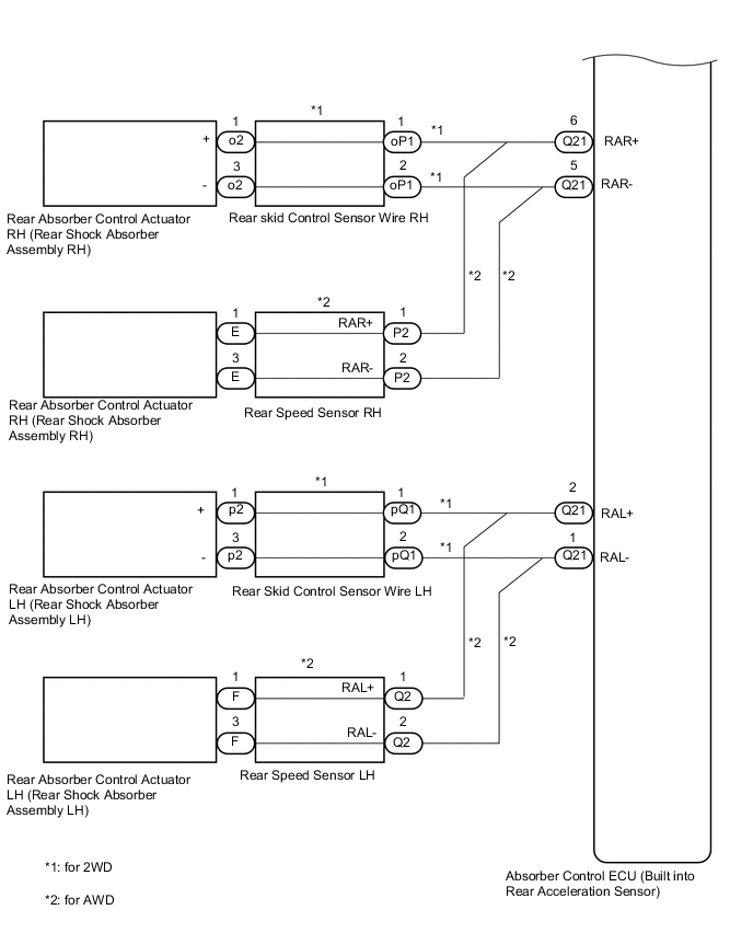
WIRING DIAGRAM
CAUTION / NOTICE / HINT
Note
-
Before performing troubleshooting, inspect the connectors of related circuits.
-
If DTC C1782 (Power Source Voltage Malfunction) is output at the same time, perform troubleshooting for C1782 first.
-
Before replacing the absorber control ECU, perform all of the following again: 1) symptom simulation ; 2) DTC inspection; and 3) GTS inspection (ECU Data List or Active Test Click here). If no malfunctions are found in other areas, replace the absorber control ECU.
-
When the absorber control ECU is replaced, switch to test mode and check that all test mode DTCs are cleared when their respective deletion conditions are met.
PROCEDURE
-
CLEAR DTC
-
Clear the DTCs.
Chassis > Air suspension > Clear DTCsResult Proceed to NEXT
NEXT 
-
-
PERFORM ACTIVE TEST USING GTS (DAMPER STEP)
-
Turn the power switch off.
-
Connect the GTS to the DLC3.
-
Turn the power switch on (READY).
-
Turn the GTS on.
-
Enter the following menus: Chassis / Air suspension /Active Test.
Chassis > Air suspension > Active TestTester Display Measurement Item Control Range Diagnostic Note Damper Step FR Changes damper step (front RH) 1 to 30 step The shock absorber hardens as the damper step increases. Damper Step FL Changes damper step (front LH) 1 to 30 step The shock absorber hardens as the damper step increases. Damper Step RR Changes damper step (rear RH) 1 to 30 step The shock absorber hardens as the damper step increases. Damper Step RL Changes damper step (rear LH) 1 to 30 step The shock absorber hardens as the damper step increases.
Chassis > Air suspension > Active TestTester Display Damper Step FR
Chassis > Air suspension > Active TestTester Display Damper Step FL
Chassis > Air suspension > Active TestTester Display Damper Step RR
Chassis > Air suspension > Active TestTester Display Damper Step RL -
When performing the Active Test, read each Tester Display item for the applicable wheel on the Data List and check the operation status of the absorber control actuator for the applicable wheel.
Chassis > Air suspension > Data ListTester Display Measurement Item Range Normal Condition Diagnostic Note Damper Step FR Damper step (front RH) Min.: 1 step
Max.: 255 step
1 to 30 step - Damper Step FL Damper step (front LH) Min.: 1 step
Max.: 255 step
1 to 30 step - Damper Step RR Damper step (rear RH) Min.: 1 step
Max.: 255 step
1 to 30 step - Damper Step RL Damper step (rear LH) Min.: 1 step
Max.: 255 step
1 to 30 step - FR Solenoid Aim Electric Current Level for Control Target solenoid current value (front wheel RH) Min.: 0 mA
Max.: 2040 mA
Changes depending on step count - FL Solenoid Aim Electric Current Level for Control Target solenoid current value (front wheel LH) Min.: 0 mA
Max.: 2040 mA
Changes depending on step count - RR Solenoid Aim Electric Current Level for Control Target solenoid current value (rear wheel RH) Min.: 0 mA
Max.: 2040 mA
Changes depending on step count - RL Solenoid Aim Electric Current Level for Control Target solenoid current value (rear wheel LH) Min.: 0 mA
Max.: 2040 mA
Changes depending on step count - FR Solenoid Drive Duty Solenoid drive duty value (front wheel RH) Min.: 0%
Max.: 100%
Changes depending on step count - FL Solenoid Drive Duty Solenoid drive duty value (front wheel LH) Min.: 0%
Max.: 100%
Changes depending on step count - RR Solenoid Drive Duty Solenoid drive duty value (rear wheel RH) Min.: 0%
Max.: 100%
Changes depending on step count - RL Solenoid Drive Duty Solenoid drive duty value (rear wheel LH) Min.: 0%
Max.: 100%
Changes depending on step count - FR Solenoid Electric Current Solenoid current value (front wheel RH) Min.: 0 mA
Max.: 2040 mA
Changes depending on step count - FL Solenoid Electric Current Solenoid current value (front wheel LH) Min.: 0 mA
Max.: 2040 mA
Changes depending on step count - RR Solenoid Electric Current Solenoid current value (rear wheel RH) Min.: 0 mA
Max.: 2040 mA
Changes depending on step count - RL Solenoid Electric Current Solenoid current value (rear wheel LH) Min.: 0 mA
Max.: 2040 mA
Changes depending on step count -
Chassis > Air suspension > Data ListTester Display Damper Step FR Damper Step FL Damper Step RR Damper Step RL FR Solenoid Aim Electric Current Level for Control FL Solenoid Aim Electric Current Level for Control RR Solenoid Aim Electric Current Level for Control RL Solenoid Aim Electric Current Level for Control FR Solenoid Drive Duty FL Solenoid Drive Duty RR Solenoid Drive Duty RL Solenoid Drive Duty FR Solenoid Electric Current FL Solenoid Electric Current RR Solenoid Electric Current RL Solenoid Electric Current OK The Data List step numbers, drive duty values and current values change according to the GTS Active Test operation. Result Proceed to OK NG
NG 
GO TO STEP 4 Click here
OK
-
-
RECONFIRM DTC
-
Check that the same DTC is output.
Chassis > Air suspension > Trouble CodesResult Result Proceed to DTC is output A DTC is not output B
B 
USE SIMULATION METHOD TO CHECK Click here
A
-
-
INSPECT SHOCK ABSORBER ASSEMBLY
-
Turn the power switch off.
-
Remove the absorber control actuator (shock absorber assembly).
for Front Side: Click here
for Rear Side: Click here
-
Inspect the absorber control actuator (shock absorber assembly).
for Front Side: Click here
for Rear Side: Click here
Result Result Proceed to OK (for Front Side) A OK (for Rear Side) B Front absorber control actuator RH (front shock absorber assembly RH) malfunction C Front absorber control actuator LH (front shock absorber assembly LH) malfunction D Rear absorber control actuator RH (rear shock absorber assembly RH) malfunction E Rear absorber control actuator LH (rear shock absorber assembly LH) malfunction F
B
INSPECT REAR SKID CONTROL SENSOR WIRE OR REAR SPEED SENSOR Click here
C
REPLACE FRONT SHOCK ABSORBER ASSEMBLY RH Click here
D
REPLACE FRONT SHOCK ABSORBER ASSEMBLY LH Click here
E
REPLACE REAR SHOCK ABSORBER ASSEMBLY RH Click here
F
REPLACE REAR SHOCK ABSORBER ASSEMBLY LH Click here
A
-
-
INSPECT FRONT SKID CONTROL SENSOR WIRE
-
Turn the power switch off.
-
Disconnect the A64 or A65 front skid control sensor wire connector.
-
Disconnect the C or D front skid control sensor wire connector.
-
Measure the resistance according to the value(s) in the table below.
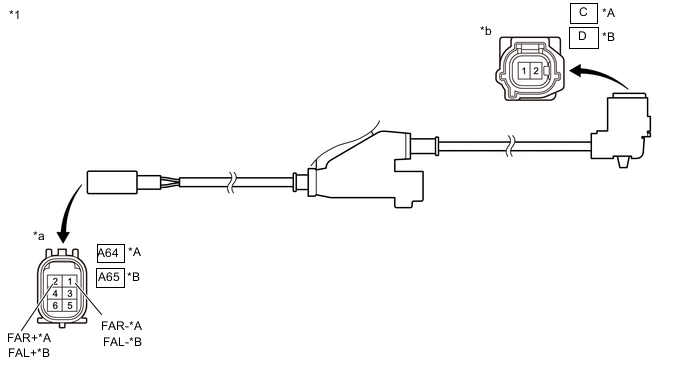
*A for RH *B for LH *1 Front Skid Control Sensor Wire - - *a Front view of wire harness connector
(to Vehicle Side Connector)
*b Front view of wire harness connector
(to Front Absorber Control Actuator Side Connector)
Standard Resistance for Front RH Tester Connection Condition Specified Condition A64-2 (FAR+) - C-2 Always Below 1 Ω A64-1 (FAR-) - C-1 Always A64-2 (FAR+) or C-2 - Body ground and other terminals Always 10 kΩ or higher A64-1 (FAR-) or C-1 - Body ground and other terminals Always for Front LH: Tester Connection Condition Specified Condition A65-2 (FAL+) - D-2 Always Below 1 Ω A65-1 (FAL-) - D-1 Always A65-2 (FAL+) or D-2 - Body ground and other terminals Always 10 kΩ or higher A65-1 (FAL-) or D-1- Body ground and other terminals Always Result Proceed to OK NG
NG
REPLACE FRONT SKID CONTROL SENSOR WIRE Click here
OK
-
-
CHECK HARNESS AND CONNECTOR (FRONT SHOCK ABSORBER ASSEMBLY - ABSORBER CONTROL ECU)
-
Turn the power switch off.
-
Disconnect the Q22 absorber control ECU connector.
-
Connect the A64 or A65 front skid control sensor wire connector.
-
Measure the resistance according to the value(s) in the table below.
Standard Resistance for Front RH Tester Connection Condition Specified Condition Q22-5 (FAR+) - C-2 Always Below 1 Ω Q22-6 (FAR-) - C-1 Q22-5 (FAR+) or C-2 - Body ground Always 10 kΩ or higher Q22-6 (FAR-) or C-1 - Body ground for Front LH Tester Connection Condition Specified Condition Q22-2 (FAL+) - D-2 Always Below 1 Ω Q22-3 (FAL-) - D-1 Q22-2 (FAL+) or D-2 - Body ground Always 10 kΩ or higher Q22-3 (FAL-) or D-1 - Body ground Result Proceed to OK NG
OK
REPLACE ABSORBER CONTROL ECU Click here
NG
REPAIR OR REPLACE HARNESS OR CONNECTOR
-
-
INSPECT REAR SKID CONTROL SENSOR WIRE OR REAR SPEED SENSOR
-
Turn the power switch off.
-
for 2WD:
-
Disconnect the oP1 or pQ1 rear skid control sensor wire connector.
-
Disconnect the o2 or p2 rear skid control sensor wire connector.
-
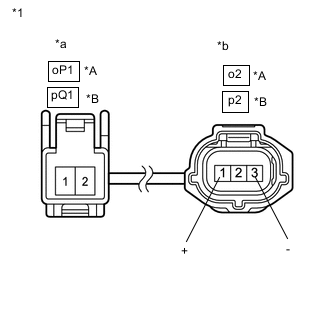
*A for RH *B for LH *1 Rear Skid Control Sensor Wire *a Front view of wire harness connector
(to Vehicle Side Connector)
*b Front view of wire harness connector
(to Rear Absorber Control Actuator Side Connector)
Measure the resistance according to the value(s) in the table below.
Standard Resistance for Rear RH Tester Connection Condition Specified Condition oP1-1 - o2-1 (+) Always Below 1 Ω oP1-2 - o2-3 (-) Always oP1-1 or o2-1 (+) - Body ground and other terminals Always 10 kΩ or higher oP1-2 or o2-3 (-) - Body ground and other terminals Always for Rear LH Tester Connection Condition Specified Condition pQ1-1 - p2-1 (+) Always Below 1 Ω pQ1-2 - p2-3 (-) Always pQ1-1 or p2-1 (+) - Body ground and other terminals Always 10 kΩ or higher pQ1-2 or p2-3 (-) - Body ground and other terminals Always
-
-
for AWD:
-
Disconnect the P2 or Q2 rear speed sensor connector.
-
Disconnect the E or F rear speed sensor connector.
-
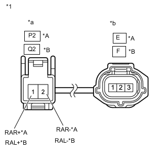
*A for RH *B for LH *1 Rear Speed Sensor *a Front view of wire harness connector
(to Vehicle Side Connector)
*b Front view of wire harness connector
(to Rear Absorber Control Actuator Side Connector)
Measure the resistance according to the value(s) in the table below.
Standard Resistance for Rear RH Tester Connection Condition Specified Condition P2-1 (RAR+) - E-1 Always Below 1 Ω P2-2 (RAR-) - E-3 Always P2-1 (RAR+) or E-1 - Body ground and other terminals Always 10 kΩ or higher P2-2 (RAR-) or E-3 - Body ground and other terminals Always for Rear LH Tester Connection Condition Specified Condition Q2-1 (RAL+) - F-1 Always Below 1 Ω Q2-2 (RAL-) - F-3 Always Q2-1 (RAL+) or F-1- Body ground and other terminals Always 10 kΩ or higher Q2-2 (RAL-) or F-3 - Body ground and other terminals Always
Result Proceed to OK NG (for 2WD) NG (for AWD) -
NG (for 2WD)
REPLACE REAR SKID CONTROL SENSOR WIRE Click here
NG (for AWD)
REPLACE REAR SPEED SENSOR Click here
OK
-
-
CHECK HARNESS AND CONNECTOR (REAR SHOCK ABSORBER ASSEMBLY - ABSORBER CONTROL ECU)
-
Turn the power switch off.
-
for 2WD:
-
Disconnect the Q21 absorber control ECU connector.
-
Connect the oP1 or pQ1 rear skid control sensor wire connector.
-
Measure the resistance according to the value(s) in the table below.
Standard Resistance for Rear RH Tester Connection Condition Specified Condition Q21-6 (RAR+) - o2-1 (+) Always Below 1 Ω Q21-5 (RAR-) - o2-3 (-) Q21-6 (RAR+) or o2-1 (+) - Body ground Always 10 kΩ or higher Q21-5 (RAR-) or o2-3 (-) - Body ground for Rear LH Tester Connection Condition Specified Condition Q21-2 (RAL+) - p2-1 (+) Always Below 1 Ω Q21-1 (RAL-) - p2-3 (-) Q21-2 (RAL+) or p2-1 (+) - Body ground Always 10 kΩ or higher Q21-1 (RAL-) or p2-3 (-) - Body ground
-
-
for AWD:
-
Disconnect the Q21 absorber control ECU connector.
-
Connect the P2 or Q2 rear speed sensor connector.
-
Measure the resistance according to the value(s) in the table below.
Standard Resistance for Rear RH Tester Connection Condition Specified Condition Q21-6 (RAR+) - E-1 Always Below 1 Ω Q21-5 (RAR-) - E-3 Q21-6 (RAR+) or E-1 - Body ground Always 10 kΩ or higher Q21-5 (RAR-) or E-3 - Body ground for Rear LH Tester Connection Condition Specified Condition Q21-2 (RAL+) - F-1 Always Below 1 Ω Q21-1 (RAL-) - F-3 Q21-2 (RAL+) or F-1 - Body ground Always 10 kΩ or higher Q21-1 (RAL-) or F-3 - Body ground
Result Proceed to OK NG -
OK
REPLACE ABSORBER CONTROL ECU Click here
NG
REPAIR OR REPLACE HARNESS OR CONNECTOR
-