REAR AXLE CARRIER INSTALLATION

CAUTION / NOTICE / HINT
Note
-
When the brake pedal is first depressed after replacing the brake pads or pushing back the disc brake piston, DTC C1214 may be output. As there is no malfunction, clear the DTC.
-
While the auxiliary battery is connected, even if the power switch is off, the brake control system activates when the brake pedal is depressed or the door courtesy switch is turned on. Therefore, even if only brake shoes are to be removed and installed, be sure to perform the Disable Brake Control procedure and disconnect the cable from the negative (-) terminal of the auxiliary battery before beginning work.
Tech Tips
-
Use the same procedure for the RH and LH sides.
-
The procedure listed below is for the LH side.
PROCEDURE
-
INSTALL REAR AXLE CARRIER SUB-ASSEMBLY LH
-
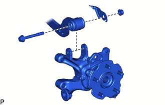
Temporarily install the rear axle carrier to the rear upper control arm with the bolt, parking brake wire bracket and nut.
-
-
TEMPORARILY INSTALL REAR NO. 2 SUSPENSION ARM ASSEMBLY LH
-
Install the rear lower coil spring insulator to the rear No. 2 suspension arm.
-
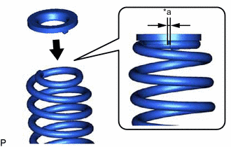
*a 10 mm or less Install the rear upper coil spring insulator to the rear coil spring.
Note
Install the rear upper coil insulator so that the distance between the stopper and upper end of the rear coil spring is 10 mm (0.394 in.) or less.
-
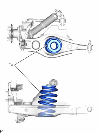
*a Identification Mark Install the rear coil spring to the rear No. 2 suspension arm.
Note
Make sure that the identification mark is positioned towards the outer sides of the vehicle.
-
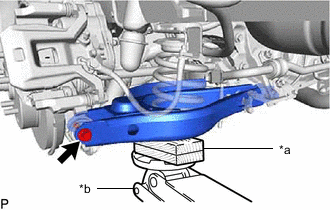
*a Wooden Block *b Jack Using a jack and wooden block, raise the vehicle gradually to install the rear No. 2 suspension arm to the rear axle carrier. Then temporarily install the bolt.
Note
-
When jacking up the rear No. 2 suspension arm assembly, be sure to jack it up slowly.
-
Do not jack up the rear No. 2 suspension arm assembly too high as the vehicle may fall.
-
Make sure to perform this operation with the vehicle kept as low as possible.
-
-
-
INSTALL REAR TRAILING ARM ASSEMBLY
-
Install the rear trailing arm to the axle carrier with the 2 bolts.
- Torque:
- 200 N*m { 2039 kgf*cm, 148 ft.*lbf }
-
-
INSTALL REAR NO. 1 SUSPENSION ARM ASSEMBLY LH
-
Install the rear No. 1 suspension arm to the rear axle carrier with a new nut.
- Torque:
- 100 N*m { 1020 kgf*cm, 74 ft.*lbf }
-
-
INSTALL REAR NO. 1 SHOCK ABSORBER BRACKET LH
-
Install the rear shock absorber bracket to the rear axle carrier with the 2 bolts.
- Torque:
- 83 N*m { 846 kgf*cm, 61 ft.*lbf }
-
-
INSTALL REAR HEIGHT CONTROL SENSOR SUB-ASSEMBLY LH
-
STABILIZE SUSPENSION
-
TIGHTEN REAR UPPER CONTROL ARM ASSEMBLY LH
-
Tighten the bolt.
- Torque:
- 90 N*m { 918 kgf*cm, 66 ft.*lbf }
Note
Since a stopper nut is used, tighten the bolt.
-
-
TIGHTEN REAR NO. 2 SUSPENSION ARM ASSEMBLY LH
-
Tighten the bolts of the suspension arm.
- Torque:
- 90 N*m { 918 kgf*cm, 66 ft.*lbf }
-
-
INSTALL REAR DISC BRAKE DUST COVER SUB-ASSEMBLY LH
-
Install the rear disc brake dust cover sub-assembly LH to the rear axle carrier with the nut.
- Torque:
- 140 N*m { 1428 kgf*cm, 103 ft.*lbf }
-
-
CONNECT PARKING BRAKE WIRE ASSEMBLY NO.1
-
INSTALL REAR STABILIZER LINK ASSEMBLY LH
-
INSTALL REAR AXLE HUB AND BEARING ASSEMBLY LH (for 2WD)
-
INSTALL REAR AXLE HUB AND BEARING ASSEMBLY LH (for AWD)
-
INSTALL REAR DISC
-
CONNECT REAR DISC BRAKE CALIPER ASSEMBLY LH
-
TEMPORARILY INSTALL REAR AXLE SHAFT NUT LH (for AWD)
-
INSPECT REAR AXLE HUB BEARING LOOSENESS
-
INSPECT REAR AXLE HUB RUNOUT
-
CONNECT REAR SKID CONTROL SENSOR WIRE LH (for 2WD)
-
w/ AVS:
-
w/o AVS:
-
-
CONNECT REAR SPEED SENSOR LH (for AWD)
-
w/ AVS:
-
w/o AVS:
-
-
STAKE REAR AXLE SHAFT NUT LH (for AWD)
-
INSTALL REAR SUSPENSION ARM COVER LH
-
INSTALL REAR WHEEL
-
INSPECT AND ADJUST REAR WHEEL ALIGNMENT
-
CHECK FOR SPEED SENSOR SIGNAL
-
CONNECT CABLE TO NEGATIVE AUXILIARY BATTERY TERMINAL
-
Connect the cable to the negative (-) auxiliary battery terminal and tighten the nut.
- Torque:
- 5.4 N*m { 55 kgf*cm, 48 in.*lbf }
-
w/o Spare tire:
Install the battery service cover and attach the 2 claws.
-
-
PERFORM INITIALIZATION