REAR AXLE CARRIER REMOVAL

CAUTION / NOTICE / HINT
Note
-
When the brake pedal is first depressed after replacing the brake pads or pushing back the disc brake piston, DTC C1214 may be output. As there is no malfunction, clear the DTC.
-
While the auxiliary battery is connected, even if the power switch is off, the brake control system activates when the brake pedal is depressed or the door courtesy switch is turned on. Therefore, even if only brake shoes are to be removed and installed, be sure to perform the Disable Brake Control procedure and disconnect the cable from the negative (-) terminal of the auxiliary battery before beginning work.
Tech Tips
-
Use the same procedure for the RH and LH sides.
-
The procedure listed below is for the LH side.
PROCEDURE
-
PRECAUTION
Note
After turning the power switch off, waiting time may be required before disconnecting the cable from the negative (-) auxiliary battery terminal. Therefore, make sure to read the disconnecting the cable from the negative (-) auxiliary battery terminal notice before proceeding with work.
-
DISABLE BRAKE CONTROL
-
REMOVE REAR WHEEL
-
REMOVE REAR AXLE SHAFT NUT LH (for AWD)
-
DISCONNECT REAR SKID CONTROL SENSOR WIRE LH (for 2WD)
-
w/ AVS:
-
w/o AVS:
-
-
DISCONNECT REAR SPEED SENSOR LH (for AWD)
-
w/ AVS:
-
w/o AVS:
-
-
DISCONNECT REAR DISC BRAKE CALIPER ASSEMBLY LH
-
REMOVE REAR DISC
-
REMOVE REAR AXLE HUB AND BEARING ASSEMBLY LH (for 2WD)
-
REMOVE REAR AXLE HUB AND BEARING ASSEMBLY LH (for AWD)
-
REMOVE REAR STABILIZER LINK ASSEMBLY LH
-
DISCONNECT PARKING BRAKE WIRE ASSEMBLY NO.1
-
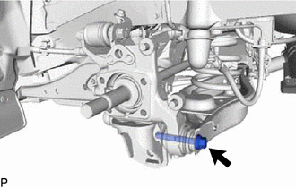
REMOVE REAR DISC BRAKE DUST COVER SUB-ASSEMBLY LH
-
Remove the nut and the rear disc brake dust cover sub-assembly LH from the rear axle carrier.
-
-
REMOVE REAR SUSPENSION ARM COVER LH
-
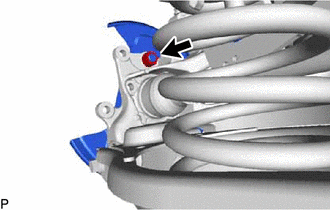
REMOVE REAR HEIGHT CONTROL SENSOR SUB-ASSEMBLY LH
-
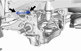
DISCONNECT REAR NO. 1 SHOCK ABSORBER BRACKET LH
-
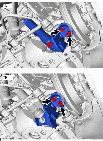
*A w/o AVS *B w/ AVS Remove the 2 bolts and disconnect the rear shock absorber bracket LH from the rear axle carrier.
-
-
DISCONNECT REAR NO. 1 SUSPENSION ARM ASSEMBLY LH
-
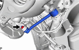
Remove the nut from the axle carrier.
-
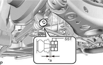
*a 1 mm (0.0394 in.) Install SST to the rear No. 1 suspension arm as shown in the illustration.
- SST
- 09960-20010 ( 09961-02060 )
Note
Make sure that the clearance measurement between SST and the rear axle assembly is 1 mm (0.0394 in.).
Tech Tips
Use 2 SST of the same type.
-
Using SST, disconnect the rear No. 1 suspension arm from the rear axle carrier as shown in the illustration.
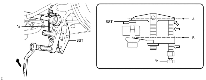
*a Tie the string without any slack. *b Place a wrench here. 
Turn 
Molybdenum Grease Application Area - SST
- 09960-20010 ( 09961-02010 )
CAUTION:
Apply molybdenum grease to the threads and end of SST bolt.
Note
-
Be sure to tighten the string firmly to secure SST to the rear axle assembly to prevent SST from falling off.
-
Install SST so that A and B are parallel.
-
Be sure to place a wrench on the part indicated in the illustration.
-
Do not damage the ball joint dust cover.
-
-
DISCONNECT REAR TRAILING ARM ASSEMBLY
-
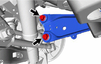
Remove the 2 bolts and disconnect the rear trailing arm from the rear axle carrier.
-
-
DISCONNECT REAR NO. 2 SUSPENSION ARM ASSEMBLY LH
-
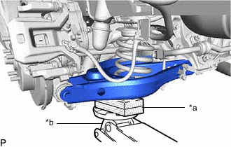
*a Wooden Block *b Jack Support the rear No. 2 suspension arm with a jack using a wooden block to avoid damage.
Note
Do not excessively jack up the rear No. 2 suspension arm assembly LH.
Tech Tips
Support the rear shock absorber at a position where it compresses by approximately 20 to 30 mm (0.788 to 1.181 in.).
-
Loosen the bolt and nut of the rear No. 2 suspension arm on the rear suspension member side.
-
Remove the bolt and disconnect the No. 2 rear suspension arm from the rear axle carrier.
-
Lower the jack gradually to remove the rear coil spring together with the rear upper coil spring insulator.
-
Remove the rear lower coil spring insulator from the rear No. 2 suspension arm.
-
-
REMOVE REAR AXLE CARRIER SUB-ASSEMBLY LH
-
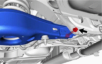
Remove the bolt and parking brake wire bracket and disconnect the rear upper control arm from the rear axle carrier.
Note
Since a stopper nut is used, remove the bolt.
-