FRONT DRIVE SHAFT ASSEMBLY REMOVAL

PROCEDURE
-
REMOVE FRONT WHEEL
-
REMOVE NO. 1 ENGINE UNDER COVER ASSEMBLY
-
REMOVE REAR ENGINE UNDER COVER LH
-
REMOVE REAR ENGINE UNDER COVER RH
-
DRAIN HYBRID TRANSAXLE FLUID
-
REMOVE FRONT AXLE SHAFT NUT LH
-
REMOVE FRONT AXLE SHAFT NUT RH
Tech Tips
Use the same procedure described for the LH side.
-
DISCONNECT FRONT SPEED SENSOR LH (w/o AVS)
-
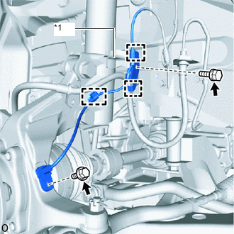
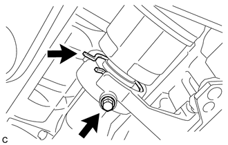
*1 Absorber Bracket Remove the clamp.
-
Remove the bolt, 2 guides and sensor clamp from the absorber bracket.
-
Remove the bolt and front speed sensor LH.
Note
Prevent foreign matter from attaching to the front speed sensor tip.
-
-
REMOVE FRONT SPEED SENSOR LH (w/ AVS)
-
Remove the front speed sensor LH.
-
Disconnect the skid control sensor wire LH.
-
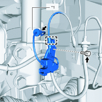
*1 Absorber Bracket Remove the bolt, guide and sensor clamp.
-
Remove the grommet from the absorber bracket.
-
-
-
DISCONNECT FRONT SPEED SENSOR RH (w/o AVS)
Tech Tips
Use the same procedure described for the LH side.
-
REMOVE FRONT SPEED SENSOR RH (w/ AVS)
Tech Tips
Use the same procedure described for the LH side.
-
DISCONNECT FRONT STABILIZER LINK ASSEMBLY LH
-
DISCONNECT FRONT STABILIZER LINK ASSEMBLY RH
Tech Tips
Use the same procedure described for the LH side.
-
DISCONNECT FRONT LOWER NO. 1 SUSPENSION ARM SUB-ASSEMBLY LH
-
DISCONNECT FRONT LOWER NO. 1 SUSPENSION ARM SUB-ASSEMBLY RH
Tech Tips
Use the same procedure described for the LH side.
-
DISCONNECT FRONT AXLE ASSEMBLY LH
-
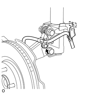
Remove the bolt and detach the 2 guides.
-
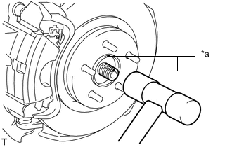
*a Matchmark Put matchmarks on the front drive shaft assembly and front axle hub sub-assembly.
-
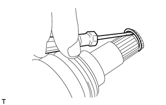
Using a plastic-faced hammer, disconnect the front drive shaft assembly from the steering knuckle with axle hub.
Note
-
Do not damage the front axle outboard joint boot and drive shaft dust cover.
-
Do not excessively push out the front drive shaft assembly LH from the front axle hub.
-
-
-
DISCONNECT FRONT AXLE ASSEMBLY RH
Tech Tips
Use the same procedure described for the LH side.
-
REMOVE FRONT DRIVE SHAFT ASSEMBLY LH
-
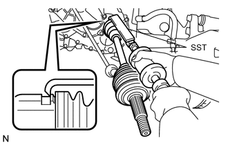
Using SST, remove the front drive shaft assembly LH.
- SST
- 09520-01010
- 09520-24010 ( 09520-32040 )
Note
-
Do not damage the front drive shaft oil seal LH, front axle inboard joint boot and front drive shaft dust cover LH.
-
Do not drop the front drive shaft assembly LH.
-
When carrying the front drive shaft assembly LH, hold it horizontally.
Tech Tips
Hook the SST claw at the position shown in the illustration to remove the front drive shaft assembly LH.
-
-
REMOVE FRONT DRIVE SHAFT ASSEMBLY RH
-
Disconnect the drive shaft bearing bracket hole snap ring from the drive shaft bearing bracket.
-
Remove the bolt and front drive shaft assembly RH from the drive shaft bearing bracket.
Note
-
Do not damage the front drive shaft oil seal RH, front axle inboard joint boot, front drive shaft dust cover RH and front drive shaft dust cover.
-
Do not drop the front drive shaft assembly RH.
-
When carrying the front drive shaft assembly RH, hold it horizontally.
Tech Tips
If the spline connection is stiff, using a brass bar and hammer, lightly tap the inboard joint assembly to remove it.
-
-
Remove the drive shaft bearing bracket hole snap ring from the front drive shaft assembly RH.
-
-
REMOVE FRONT DRIVE SHAFT HOLE SNAP RING LH
-
Using a screwdriver, remove the front drive shaft hole snap ring LH.
Note
Do not damage the spline of the front drive inboard joint assembly LH.
-