REAR TRACTION MOTOR INSTALLATION

PROCEDURE
-
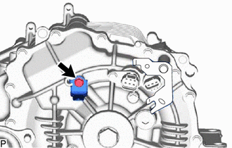
INSTALL BREATHER PLUG
-
Install the breather plug to the rear traction motor with transaxle assembly.
- Torque:
- 20.6 N*m { 210 kgf*cm, 15 ft.*lbf }
-
-
TEMPORARILY INSTALL FRONT DIFFERENTIAL SUPPORT ASSEMBLY
-
Temporarily install the front differential support assembly to the rear traction motor with transaxle assembly with the 2 bolts.
-
-
INSTALL WIRE HARNESS CLAMP BRACKET
-
Install the wire harness clamp bracket to the rear traction motor with transaxle assembly with the bolt.
- Torque:
- 7.7 N*m { 79 kgf*cm, 68 in.*lbf }
-
-
INSTALL DIFFERENTIAL MOUNT CUSHION
-
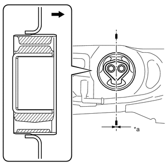
*a -3 to 3° 
Rear of vehicle Temporarily install the differential mount cushion to the rear suspension member sub-assembly from the rear of the vehicle.
-
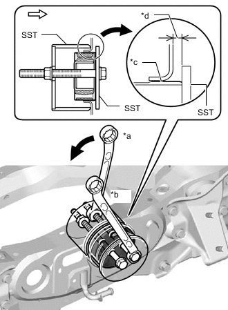
*a Turn *b Hold *c Point of engagement with rear suspension member sub-assembly *d 5.0 to 6.0 mm (0.1969 to 0.2362 in.) 
Rear of vehicle Using SST, install a new differential mount cushion.(*1)
- SST
- 09570-48010
Note
-
Before using SST, apply grease to SST bolts.
-
Do not tilt the bolts of SST.
-
Tighten the 2 bolts of SST so that they enter the 2 holes of the rear No. 1 differential mount cushion by an equal amount.
-
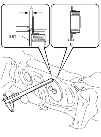
Using a vernier caliper, measure the distance labeled A in the illustration. (*2)
Note
-
Measure at several points to check that the differential mount cushion is uniformly inserted.
-
Measure at points where there is no welding bead.
-
-
Repeat steps *1 and *2 above to press the differential mount cushion into the rear suspension member sub-assembly until the distance labeled A in the illustration reaches the reference value.
Reference 11 to 12 mm (0.4331 to 0.4724 in.) -
Remove SST, and then using a vernier caliper, measure the protrusion (labeled B in the illustration) of the differential mount cushion. Check that the measured value is within the specified range.
Standard 5.0 to 6.0 mm (0.1969 to 0.2362 in.)
-
-
INSTALL REAR TRACTION MOTOR WITH TRANSAXLE ASSEMBLY
-
Using an engine sling device and chain block, hold the rear traction motor with transaxle assembly.
CAUTION:
As the rear traction motor with transaxle assembly is heavy, hold it securely using an engine sling device and chain block.
Note
-
Do not drop the rear traction motor with transaxle assembly.
-
Do not damage the installation surface of the rear traction motor with transaxle assembly.
-
-
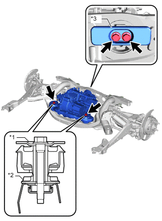
*1 Upper Differential Mount Stopper *2 Lower Differential Mount Stopper *3 Differential Dynamic Damper Temporarily install the 2 upper differential mount stoppers, 2 lower differential mount stoppers, differential dynamic damper and rear traction motor with transaxle assembly to the rear suspension member sub-assembly with the 4 bolts.
-
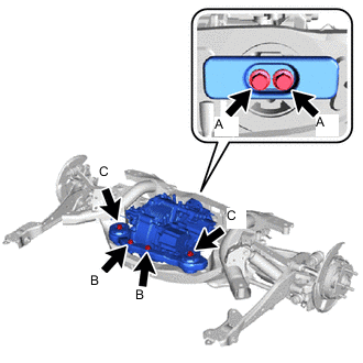
Tighten the 6 bolts.
- Torque:
- Bolt (A)
- 95.1 N*m { 970 kgf*cm, 70 ft.*lbf }
- Bolt (B)
- 80 N*m { 816 kgf*cm, 59 ft.*lbf }
- Bolt (C)
- 86 N*m { 877 kgf*cm, 63 ft.*lbf }
-
Remove the engine sling device.
-
-
INSTALL EXTENSION WIRE ASSEMBLY
CAUTION:
Be sure to wear insulated gloves.
-
Install the extension wire assembly to the rear traction motor with transaxle assembly with the 3 bolts.
- Torque:
- 10 N*m { 102 kgf*cm, 7 ft.*lbf }
Note
Firmly insert the extension wire assembly to the rear traction motor.
-
-
INSTALL REAR SUSPENSION MEMBER SUB-ASSEMBLY
-
CONNECT WIRE HARNESS
CAUTION:
Be sure to wear insulated gloves.
-
Connect the No. 2 frame wire to the rear traction motor with transaxle assembly and vehicle body with the 2 nuts.
- Torque:
- 15 N*m { 153 kgf*cm, 11 ft.*lbf }
-
Engage the 5 clamps.
-
Connect the resolver sensor connector.
-
Connect the temperature sensor connector.
-
-
INSTALL REAR DRIVE SHAFT ASSEMBLY
-
INSTALL INVERTER RESERVE TANK ASSEMBLY
-
CONNECT WIRE HARNESS
-
ADD HYBRID TRANSAXLE FLUID
-
INSPECT HYBRID TRANSAXLE FLUID
-
INSTALL SERVICE PLUG GRIP