REAR TRACTION MOTOR REMOVAL

PROCEDURE
-
REMOVE SERVICE PLUG GRIP
-
DISCONNECT WIRE HARNESS
-
REMOVE INVERTER RESERVE TANK ASSEMBLY
-
REMOVE CONNECTOR COVER ASSEMBLY
-
CHECK TERMINAL VOLTAGE
-
INSTALL CONNECTOR COVER ASSEMBLY
-
REMOVE REAR DRIVE SHAFT ASSEMBLY
-
DRAIN HYBRID TRANSAXLE FLUID
-
DISCONNECT WIRE HARNESS
-
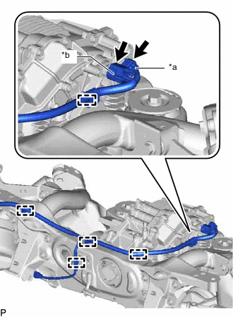
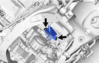
*a Temperature Sensor Connector *b Resolver Sensor Connector Disconnect the temperature sensor connector.
-
Disconnect the resolver sensor connector.
-
Disengage the 5 clamps.
-
Remove the 2 nuts and disconnect the No. 2 frame wire from the rear traction motor with transaxle assembly and vehicle body.
-
-
REMOVE REAR SUSPENSION MEMBER SUB-ASSEMBLY
-
REMOVE REAR TRACTION MOTOR WITH TRANSAXLE ASSEMBLY
-
Using an engine sling device and chain block, hold the rear traction motor with transaxle assembly.
CAUTION:
As the rear traction motor with transaxle assembly is heavy, hold it securely using an engine sling device and chain block.
Note
-
When removing the 2 bolts on the differential mount cushion side of the rear traction motor with transaxle assembly, make sure to hold the rear traction motor with transaxle assembly securely to prevent it from dropping.
-
Lightly shake the rear traction motor with transaxle assembly by hand to make sure it is securely held while performing work.
-
Do not shake the rear traction motor with transaxle assembly excessively while holding it.
-
-
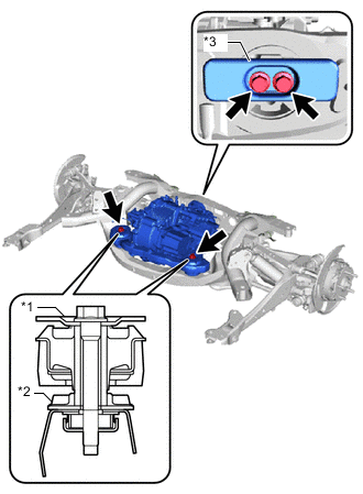
*1 Upper Differential Mount Stopper *2 Lower Differential Mount Stopper *3 Differential Dynamic Damper Remove the 4 bolts, 2 upper differential mount stoppers, 2 lower differential mount stoppers, differential dynamic damper and rear traction motor with transaxle assembly from the rear suspension member sub-assembly.
Note
-
Do not drop the rear traction motor with transaxle assembly.
-
Do not damage the installation surface of the rear traction motor with transaxle assembly.
-
-
-
REMOVE EXTENSION WIRE ASSEMBLY
-
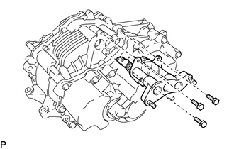
Remove the 3 bolts and extension wire assembly from the rear traction motor with transaxle assembly.
-
-
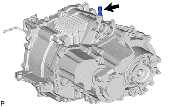
REMOVE WIRE HARNESS CLAMP BRACKET
-
Remove the bolt and wire harness clamp bracket from the rear traction motor with transaxle assembly.
-
-
REMOVE FRONT DIFFERENTIAL SUPPORT ASSEMBLY
-
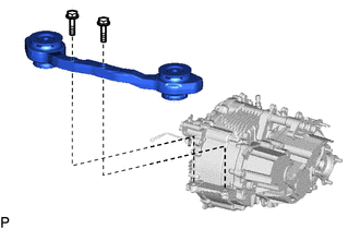
Remove the 2 bolts and front differential support assembly from the rear traction motor with transaxle assembly.
-
-
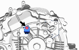
REMOVE BREATHER PLUG
-
Remove the breather plug from the rear traction motor with transaxle assembly.
-
-
REMOVE DIFFERENTIAL MOUNT CUSHION
-
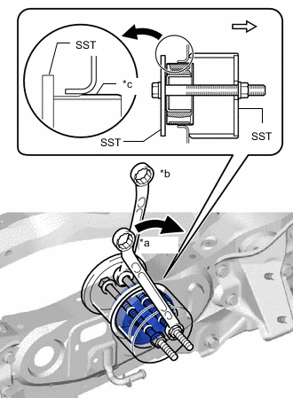
*a Turn *b Hold *c Point of engagement with rear suspension member sub-assembly 
Rear of vehicle Using SST, remove the differential mount cushion.
- SST
- 09570-48010
Note
-
Before using SST, apply grease to SST bolts.
-
Tighten the 2 bolts of SST so that they enter the 2 holes of the differential mount cushion by an equal amount.
-
Do not tilt the bolts of SST.
-
Tighten SST until differential mounting cushion and rear suspension member sub-assembly disengage.
-