SHIFT LEVER POSITION SENSOR INSTALLATION
PROCEDURE
-
INSTALL SHIFT LEVER POSITION SENSOR
-
Install the shift lever position sensor to the manual valve shaft.
-
Temporarily install the 2 bolts.
-
Install the lock plate and tighten the lock nut.
- Torque:
- 6.9 N*m { 70 kgf*cm, 61 in.*lbf }
-
Temporarily install the control shaft lever to the manual valve shaft.
-
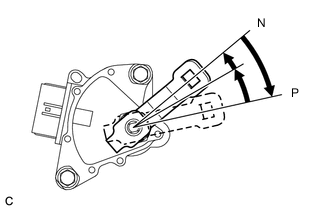
Turn the control shaft lever clockwise until it stops, and then turn it counterclockwise 2 notches.
-
Remove the control shaft lever from the manual valve shaft.
-
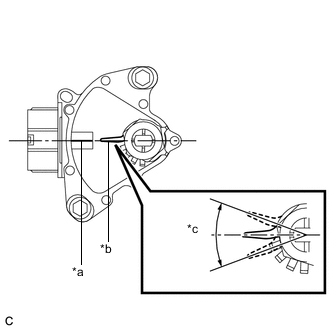
*a Neutral Basic Line *b Protruding *c Range of Play Align the protruding part with the neutral basic line.
Note
There is play in the nut stopper (protruding part). Position the protruding part so that it is aligned with the neutral basic line when it is in the center of its range of play.
-
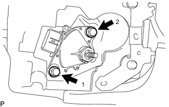
Tighten the 2 bolts in the order shown in the illustration.
- Torque:
- 13 N*m { 133 kgf*cm, 10 ft.*lbf }
-
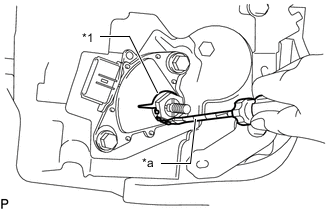
*1 Lock Plate *a Protective Tape Using a screwdriver with its tip wrapped with protective tape, secure the lock nut with the lock plate.
-
Install the control shaft lever, washer, and nut to the manual valve shaft.
- Torque:
- 12.7 N*m { 130 kgf*cm, 9 ft.*lbf }
-
Connect the shift lever position sensor connector.
-
-
CONNECT TRANSMISSION CONTROL CABLE ASSEMBLY
-
Move the shift lever to N.
-
Install a new clip to the No. 1 transmission control cable bracket.
-
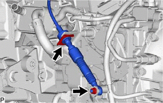
Connect the transmission control cable assembly to the control shaft lever with the nut.
- Torque:
- 12 N*m { 122 kgf*cm, 9 ft.*lbf }
-
-
INSPECT SHIFT LEVER POSITION SENSOR POSITION
-
ADJUST SHIFT LEVER POSITION SENSOR POSITION
-
INSPECT SHIFT LEVER POSITION
-
ADJUST SHIFT LEVER POSITION
-
INSTALL NO. 1 ENGINE UNDER COVER ASSEMBLY