SHIFT LEVER POSITION SENSOR INSPECTION
PROCEDURE
-
INSPECT SHIFT LEVER POSITION SENSOR
-
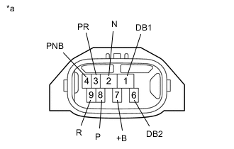
*a Component without harness connected
(Shift Lever Position Sensor)
Measure the resistance according to the value(s) in the table below.
Standard Resistance Tester Connection Condition Specified Condition 7 (+B) - 3 (PR) Shift lever in P Below 1 Ω 7 (+B) - 4 (PNB) Below 1 Ω 7 (+B) - 8 (P) Below 1 Ω 7 (+B) - 1 (DB1), 2 (N), 6 (DB2) and 9 (R) 10 kΩ or higher 7 (+B) - 3 (PR) Shift lever in R Below 1 Ω 7 (+B) - 9 (R) Below 1 Ω 7 (+B) - 1 (DB1), 2 (N), 4 (PNB), 6 (DB2) and 8 (P) 10 kΩ or higher 7 (+B) - 2 (N) Shift lever in N Below 1 Ω 7 (+B) - 4 (PNB) Below 1 Ω 7 (+B) - 1 (DB1), 3 (PR), 6 (DB2), 8 (P) and 9 (R) 10 kΩ or higher 7 (+B) - 1 (DB1) Shift lever in D Below 1 Ω 7 (+B) - 6 (DB2) Below 1 Ω 7 (+B) - 2 (N), 3 (PR), 4 (PNB), 8 (P) and 9 (R) 10 kΩ or higher 7 (+B) - 1 (DB1) Shift lever in B Below 1 Ω 7 (+B) - 4 (PNB) Below 1 Ω 7 (+B) - 6 (DB2) Below 1 Ω 7 (+B) - 2 (N), 3 (PR), 8 (P) and 9 (R) 10 kΩ or higher If the result is not as specified, replace the shift lever position sensor.
-