DYNAMIC RADAR CRUISE CONTROL SYSTEM, Diagnostic DTC:C1A4B
| DTC Code | DTC Name |
|---|---|
| C1A4B | Stop Light Relay Circuit |
DESCRIPTION
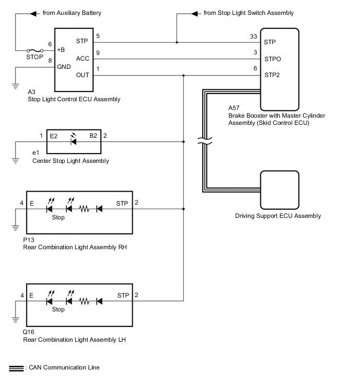
The brake booster with master cylinder assembly (skid control ECU) sends a stop light operation signal to the stop light control ECU assembly. When the brake booster with master cylinder assembly (skid control ECU) detects a malfunction in the stop light circuit, the driving support ECU assembly stores DTC C1A4B.
| Vehicle Condition | |||
|---|---|---|---|
| Pattern 1 | Pattern 2 | ||
| Diagnosis Condition | IG1 terminal voltage is 11 to 14 V | ○ | ○ |
| When the vehicle speed is approximately 50 km/h (30 mph) or more, the cruise control switch (ON/OFF) is on | ○ | ○ | |
| Stop Light illumination output (STPO) ON | ○ | - | |
| Stop Light illumination output (STPO) OFF | - | ○ | |
| Malfunction Status | No signal input to STP2 terminal | ○ | - |
| Signals input to STP and STP2 terminals do not match | - | ○ | |
| Malfunction Time | 0.3 seconds or more | 0.3 seconds or more | |
| Number of Trips | - | - | |
| DTC No. | Detection Item | DTC Detection Condition | Trouble Area |
|---|---|---|---|
| C1A4B | Stop Light Relay Circuit | Either of the following conditions is met:
|
|
WIRING DIAGRAM
CAUTION / NOTICE / HINT
Note
-
First perform the communication function inspections in How to Proceed with Troubleshootingto confirm that there are no CAN communication malfunctions before troubleshooting.
-
Inspect the fuses for circuits related to this system before performing the following procedure.
-
When replacing the brake booster with master cylinder assembly (skid control ECU), perform zero point calibration.
PROCEDURE
-
CHECK TERMINAL VOLTAGE (STP, STPO AND STP2 TERMINAL)
-
Turn the power swich off.
-

*a Front view of wire harness connector
(to Brake Booster with Master Cylinder Assembly [Skid Control ECU])
Disconnect the brake booster with master cylinder assembly (skid control ECU) connector.
-
Measure the voltage according to the value(s) in the table below.
Standard Voltage Tester Connection Condition Specified Condition A57-6 (STP2) - Body ground Brake pedal depressed 11 to 14 V Brake pedal released Below 1.5 V A57-3 (STPO) - Body ground Always 11 to 14 V A57-33 (STP) - Body ground Brake pedal depressed 11 to 14 V Brake pedal released Below 1.5 V Result Result Proceed to All terminal voltage is normal A Only STP terminal voltage abnormal B Only STPO terminal voltage abnormal C Only STP2 terminal voltage abnormal D STPO terminal and STP2 terminal voltage abnormal E
B 
REPAIR OR REPLACE HARNESS OR CONNECTOR
C 
CHECK HARNESS AND CONNECTOR (BRAKE BOOSTER WITH MASTER CYLINDER ASSEMBLY [SKID CONTROL ECU] - STOP LIGHT CONTROL ECU ASSEMBLY) Click here
D
CHECK TERMINAL VOLTAGE (STP2 TERMINAL) Click here
E
CHECK STOP LIGHT CONTROL ECU ASSEMBLY POWER SOURCE CIRCUIT Click here
A 
-
-
PERFORM ACTIVE TEST USING TECHSTREAM (STOP LIGHT RELAY)
-
Enter the following menus: Chassis / ABS/VSC/TRC / Active Test.
-
Perform "Active Test" according to the display on the GTS.
Chassis > ABS/VSC/TRC > Active TestTester Display Measurement Item Control Range Diagnostic Note Stop Light Relay Stop light control ECU assembly (stop light control relay) ECU (Relay) ON/OFF Stop lights come on
Chassis > ABS/VSC/TRC > Active TestTester Display Stop Light Relay OK Stop light turns ON/OFF in response to the GTS operation Result Proceed to OK NG
NG
INSPECT BRAKE BOOSTER WITH MASTER CYLINDER ASSEMBLY (SKID CONTROL ECU) Click here
OK
-
-
CHECK FOR DTC
-
Clear the DTCs.
Powertrain > Radar Cruise > Clear DTCs -
Enter the following menus: Chassis / ABS/VSC/TRC / Active Test.
-
Perform "Active Test" according to the display on the GTS.
Chassis > ABS/VSC/TRC > Active TestTester Display Measurement Item Control Range Diagnostic Note Stop Light Relay Stop light control ECU assembly (stop light control relay) ECU (Relay) ON/OFF Stop lights come on
Chassis > ABS/VSC/TRC > Active TestTester Display Stop Light Relay -
Check for DTCs.
Powertrain > Radar Cruise > Trouble CodesResult Result Proceed to DTC C1A4B is output A DTC C1A4B is not output B
A
REPLACE BRAKE BOOSTER WITH MASTER CYLINDER ASSEMBLY (SKID CONTROL ECU) for LHD: Click here
REPLACE BRAKE BOOSTER WITH MASTER CYLINDER ASSEMBLY (SKID CONTROL ECU) for RHD: Click hereB
USE SIMULATION METHOD TO CHECK Click here
-
-
INSPECT BRAKE BOOSTER WITH MASTER CYLINDER ASSEMBLY (SKID CONTROL ECU)
-
Enter the following menus: Chassis / ABS/VSC/TRC / Active Test.
-
Perform "Active Test" according to the display on the GTS.
Chassis > ABS/VSC/TRC > Active TestTester Display Measurement Item Control Range Diagnostic Note Stop Light Relay Stop light control ECU assembly (stop light control relay) ECU (Relay) ON/OFF Stop lights come on
Chassis > ABS/VSC/TRC > Active TestTester Display Stop Light Relay -
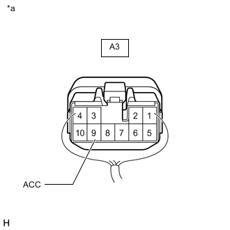
*a Component with harness connected
(Stop Light Control ECU Assembly)
Measure the voltage according to the value(s) in the table below.
Standard Voltage Tester Connection Condition Specified Condition A3-9 (ACC) - Body ground Active test is ON Below 1.5 V Result Proceed to OK NG
OK
REPLACE STOP LIGHT CONTROL ECU ASSEMBLY for LHD: Click here
REPLACE STOP LIGHT CONTROL ECU ASSEMBLY for RHD: Click hereNG
REPLACE BRAKE BOOSTER WITH MASTER CYLINDER ASSEMBLY (SKID CONTROL ECU) for LHD: Click here
REPLACE BRAKE BOOSTER WITH MASTER CYLINDER ASSEMBLY (SKID CONTROL ECU) for RHD: Click here -
-
CHECK HARNESS AND CONNECTOR (BRAKE BOOSTER WITH MASTER CYLINDER ASSEMBLY [SKID CONTROL ECU] - STOP LIGHT CONTROL ECU ASSEMBLY)
-
Turn the power switch off.
-
Disconnect the A57 brake booster with master cylinder assembly (skid control ECU) connector.
-
Disconnect the A3 stop light control ECU assembly connector.
-
Measure the resistance according to the value(s) in the table below.
Standard Resistance Tester Connection Condition Specified Condition A57-3 (STPO) - A3-9 (ACC) Always Below 1 Ω Result Proceed to OK NG
OK
REPLACE STOP LIGHT CONTROL ECU ASSEMBLY for LHD: Click here
REPLACE STOP LIGHT CONTROL ECU ASSEMBLY for RHD: Click hereNG
REPAIR OR REPLACE HARNESS OR CONNECTOR
-
-
CHECK TERMINAL VOLTAGE (STP2 TERMINAL)
-
Turn the power switch off.
-

*a Front view of wire harness connector
(to Brake Booster with Master Cylinder Assembly [Skid Control ECU])
Disconnect the brake booster with master cylinder assembly (skid control ECU) connector.
-
Measure the voltage according to the value(s) in the table below.
Standard Voltage Tester Connection Condition Specified Condition A57-6 (STP2) - Body ground Brake pedal released Below 1.5 V Result Proceed to OK NG
NG
CHECK HARNESS AND CONNECTOR (BRAKE BOOSTER WITH MASTER CYLINDER ASSEMBLY [SKID CONTROL ECU] - STOP LIGHT CONTROL ECU ASSEMBLY) Click here
OK
-
-
CHECK HARNESS AND CONNECTOR (BRAKE BOOSTER WITH MASTER CYLINDER ASSEMBLY [SKID CONTROL ECU] - REAR COMBINATION LIGHT ASSEMBLY LH)
-
Turn the power switch off.
-
Disconnect the A57 brake booster with master cylinder assembly (skid control ECU) connector.
-
Disconnect the Q16 rear combination light assembly LH connector.
-
Measure the voltage according to the value(s) in the table below.
Standard Voltage Tester Connection Condition Specified Condition A57-6 (STP2) - Body ground Brake pedal depressed 11 to 14 V Result Proceed to OK NG
OK
REPLACE REAR COMBINATION LIGHT ASSEMBLY LH Click here
NG
-
-
CHECK HARNESS AND CONNECTOR (BRAKE BOOSTER WITH MASTER CYLINDER ASSEMBLY [SKID CONTROL ECU] - REAR COMBINATION LIGHT ASSEMBLY RH)
-
Turn the power switch off.
-
Disconnect the A57 brake booster with master cylinder assembly (skid control ECU) connector.
-
Disconnect the Q16 rear combination light assembly LH connector.
-
Disconnect the P13 rear combination light assembly RH connector.
-
Measure the voltage according to the value(s) in the table below.
Standard Voltage Tester Connection Condition Specified Condition A57-6 (STP2) - Body ground Brake pedal depressed 11 to 14 V Result Proceed to OK NG
OK
REPLACE REAR COMBINATION LIGHT ASSEMBLY RH Click here
NG
-
-
CHECK HARNESS AND CONNECTOR (BRAKE BOOSTER WITH MASTER CYLINDER ASSEMBLY [SKID CONTROL ECU] - CENTER STOP LIGHT ASSEMBLY)
-
Turn the power switch off.
-
Disconnect the A57 brake booster with master cylinder assembly (skid control ECU) connector.
-
Disconnect the Q16 rear combination light assembly LH connector.
-
Disconnect the P13 rear combination light assembly RH connector.
-
Disconnect the e1 center stop light assembly connector.
-
Measure the voltage according to the value(s) in the table below.
Standard Voltage Tester Connection Condition Specified Condition A57-6 (STP2) - Body ground Brake pedal depressed 11 to 14 V Result Proceed to OK NG
OK
REPLACE CENTER STOP LIGHT ASSEMBLY Click here
NG
CHECK HARNESS AND CONNECTOR (BRAKE BOOSTER WITH MASTER CYLINDER ASSEMBLY [SKID CONTROL ECU] - STOP LIGHT CONTROL ECU ASSEMBLY) Click here
-
-
CHECK HARNESS AND CONNECTOR (BRAKE BOOSTER WITH MASTER CYLINDER ASSEMBLY [SKID CONTROL ECU] - STOP LIGHT CONTROL ECU ASSEMBLY)
-
Turn the power switch off.
-
Disconnect the A57 brake booster with master cylinder assembly (skid control ECU) connector.
-
Disconnect the A3 stop light control ECU assembly connector.
-
Measure the voltage according to the value(s) in the table below.
Standard Voltage Tester Connection Condition Specified Condition A57-6 (STP2) - Body ground Brake pedal released Below 1.5 V Result Proceed to OK NG
OK
REPLACE STOP LIGHT CONTROL ECU ASSEMBLY for LHD: Click here
REPLACE STOP LIGHT CONTROL ECU ASSEMBLY for RHD: Click hereNG
CHECK HARNESS AND CONNECTOR (BRAKE BOOSTER WITH MASTER CYLINDER ASSEMBLY [SKID CONTROL ECU] - REAR COMBINATION LIGHT ASSEMBLY LH) Click here
-
-
CHECK HARNESS AND CONNECTOR (BRAKE BOOSTER WITH MASTER CYLINDER ASSEMBLY [SKID CONTROL ECU] - STOP LIGHT CONTROL ECU ASSEMBLY)
-
Turn the power switch off.
-
Disconnect the A57 brake booster with master cylinder assembly (skid control ECU) connector.
-
Disconnect the Q16 rear combination light assembly LH connector.
-
Disconnect the P13 rear combination light assembly RH connector.
-
Disconnect the e1 center stop light assembly connector.
-
Disconnect the A3 stop light control ECU assembly connector.
-
Measure the resistance according to the value(s) in the table below.
Standard Resistance Tester Connection Condition Specified Condition A3-5 (STP) - A57-33 (STP) Always Below 1 Ω A3-1 (OUT) - A57-6 (STP2) Always Below 1 Ω A3-1 (OUT) or A57-6 (STP2) - Body ground Always 10 kΩ or higher Result Proceed to OK NG
OK
REPLACE STOP LIGHT CONTROL ECU ASSEMBLY for LHD: Click here
REPLACE STOP LIGHT CONTROL ECU ASSEMBLY for RHD: Click hereNG
REPAIR OR REPLACE HARNESS OR CONNECTOR
-
-
CHECK HARNESS AND CONNECTOR (BRAKE BOOSTER WITH MASTER CYLINDER ASSEMBLY [SKID CONTROL ECU] - REAR COMBINATION LIGHT ASSEMBLY LH)
-
Turn the power switch off.
-
Disconnect the A57 brake booster with master cylinder assembly (skid control ECU) connector.
-
Disconnect the A3 stop light control ECU assembly connector.
-
Disconnect the Q16 rear combination light assembly LH connector.
-
Measure the voltage according to the value(s) in the table below.
Standard Voltage Tester Connection Condition Specified Condition A57-6 (STP2) - Body ground Brake pedal released Below 1.5 V Result Proceed to OK NG
OK
REPLACE REAR COMBINATION LIGHT ASSEMBLY LH Click here
NG
-
-
CHECK HARNESS AND CONNECTOR (BRAKE BOOSTER WITH MASTER CYLINDER ASSEMBLY [SKID CONTROL ECU] - REAR COMBINATION LIGHT ASSEMBLY RH)
-
Turn the power switch off.
-
Disconnect the A57 brake booster with master cylinder assembly (skid control ECU) connector.
-
Disconnect the A3 stop light control ECU assembly connector.
-
Disconnect the Q16 rear combination light assembly LH connector.
-
Disconnect the P13 rear combination light assembly RH connector.
-
Measure the voltage according to the value(s) in the table below.
Standard Voltage Tester Connection Condition Specified Condition A57-6 (STP2) - Body ground Brake pedal released Below 1.5 V Result Proceed to OK NG
OK
REPLACE REAR COMBINATION LIGHT ASSEMBLY RH Click here
NG
CHECK HARNESS AND CONNECTOR (BRAKE BOOSTER WITH MASTER CYLINDER ASSEMBLY [SKID CONTROL ECU] - CENTER STOP LIGHT ASSEMBLY) Click here
-
-
CHECK STOP LIGHT CONTROL ECU ASSEMBLY POWER SOURCE CIRCUIT
-
Turn the power switch off.
-
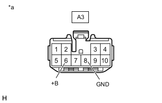
*a Front view of wire harness connector
(to Stop Light Control ECU Assembly)
Disconnect the stop light control ECU assembly connector.
-
Measure the resistance according to the value(s) in the table below.
Standard Resistance Tester Connection Condition Specified Condition A3-8 (GND) - Body ground Always Below 1 Ω -
Measure the voltage according to the value(s) in the table below.
Standard Voltage Tester Connection Switch Condition Specified Condition A3-6 (+B) - Body ground Power swich off 11 to 14 V Result Proceed to OK NG
NG
REPAIR OR REPLACE HARNESS OR CONNECTOR
OK
-
-
CHECK HARNESS AND CONNECTOR (BRAKE BOOSTER WITH MASTER CYLINDER ASSEMBLY [SKID CONTROL ECU] - STOP LIGHT CONTROL ECU ASSEMBLY)
-
Turn the power switch off.
-
Disconnect the A57 brake booster with master cylinder assembly (skid control ECU) connector.
-
Disconnect the A3 stop light control ECU assembly connector.
-
Measure the resistance according to the value(s) in the table below.
Standard Resistance Tester Connection Condition Specified Condition A57-3 (STPO) - A3-9 (ACC) Always Below 1 Ω Result Proceed to OK NG
OK
REPLACE STOP LIGHT CONTROL ECU ASSEMBLY for LHD: Click here
REPLACE STOP LIGHT CONTROL ECU ASSEMBLY for RHD: Click hereNG
REPAIR OR REPLACE HARNESS OR CONNECTOR
-
-
CHECK HARNESS AND CONNECTOR (BRAKE BOOSTER WITH MASTER CYLINDER ASSEMBLY [SKID CONTROL ECU] - CENTER STOP LIGHT ASSEMBLY)
-
Turn the power switch off.
-
Disconnect the A57 brake booster with master cylinder assembly (skid control ECU) connector.
-
Disconnect the A3 stop light control ECU assembly connector.
-
Disconnect the Q16 rear combination light assembly LH connector.
-
Disconnect the P13 rear combination light assembly RH connector.
-
Disconnect the e1 center stop light assembly connector.
-
Measure the voltage according to the value(s) in the table below.
Standard Voltage Tester Connection Condition Specified Condition A57-6 (STP2) - Body ground Brake pedal released Below 1.5 V Result Proceed to OK NG
OK
REPLACE CENTER STOP LIGHT ASSEMBLY Click here
NG
REPAIR OR REPLACE HARNESS OR CONNECTOR
-