DYNAMIC RADAR CRUISE CONTROL SYSTEM, Diagnostic DTC:C1A4A
| DTC Code | DTC Name |
|---|---|
| C1A4A | Skid Control Buzzer Circuit |
DESCRIPTION
Based on dynamic radar cruise control system operation, the driving support ECU assembly provides warnings to the driver by sounding the skid control buzzer.
DTC C1A4A is stored when a malfunction is detected in the skid control buzzer circuit.
| DTC No. | Detection Item | DTC Detection Condition | Trouble Area |
|---|---|---|---|
| C1A4A | Skid Control Buzzer Circuit |
w/o Full-speed range following function:
w/ Full-speed range following function: |
|
WIRING DIAGRAM
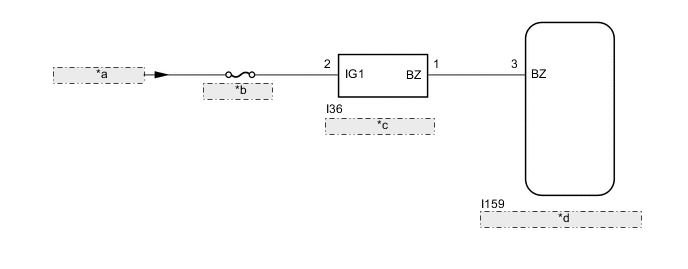
| *a | from IG Circuit |
| *b | ECU-IG NO. 2 |
| *c | Skid Control Buzzer |
| *d | Driving Support ECU Assembly |
CAUTION / NOTICE / HINT
Note
-
Inspect the fuses for circuits related to this system before performing the following procedure.
-
When replacing the driving support ECU assembly, make sure to replace it with a new one. If a device which was installed to another vehicle is used, the information stored in the driving support ECU assembly will not match the information from the vehicle, and as a result, a DTC may be stored.
PROCEDURE
-
CHECK FOR DTCs (PRE-COLLISION SYSTEM)
-
Check for DTCs of the pre-collision system.
Body Electrical > Pre-Collision 2 > Trouble CodesTech Tips
-
w/o Full-speed range following function:
The dynamic radar cruise control system only stores DTC C1A4A when the vehicle speed reaches 36 km/h (22 mph), however the pre-collision system stores this DTC at any vehicle speed. If DTC C1A4A is stored by the pre-collision system, perform troubleshooting of the pre-collision system first.
-
w/ Full-speed range following function:
The dynamic radar cruise control system only stores DTC C1A4A when the vehicle speed reaches 5 km/h (3 mph), however the pre-collision system stores this DTC at any vehicle speed. If DTC C1A4A is stored by the pre-collision system, perform troubleshooting of the pre-collision system first.
Result Result Proceed to DTC C1A4A is not output A DTC C1A4A is output B -
B 
GO TO PRE-COLLISION SYSTEM Click here
A 
-
-
CHECK FOR DTCs (RADAR CRUISE 2)
-
Clear the DTCs.
Powertrain > Radar Cruise2 > Clear DTCs -
Make sure that the DTC detection conditions are met.
Tech Tips
If the detection conditions are not met, the system cannot detect the malfunction.
-
Check for DTCs.
Powertrain > Radar Cruise2 > Trouble CodesResult Result Proceed to DTC C1A4A is not output A DTC C1A4A is output B
A
USE SIMULATION METHOD TO CHECK Click here
B
-
-
INSPECT SKID CONTROL BUZZER (CONFIRM BUZZER OPERATION)
-
Turn the power switch on (IG).
-
Check that the skid control buzzer is sounds.
Result Result Proceed to The skid control buzzer does not sound when the power switch is on (IG). A The skid control buzzer sounds continuously when the power switch is on (IG). B
B 
CHECK HARNESS AND CONNECTOR (SKID CONTROL BUZZER - DRIVING SUPPORT ECU ASSEMBLY) Click here
A
-
-
CHECK HARNESS AND CONNECTOR (SKID CONTROL BUZZER - AUXILIARY BATTERY)
-
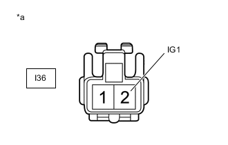
*a Front view of wire harness connector
(to Skid Control Buzzer)
Disconnect the skid control buzzer connector.
-
Measure the voltage according to the value(s) in the table below.
Standard Voltage Tester Connection Switch Condition Specified Condition I36-2 (IG1) - Body ground Power switch on (IG) 11 to 14 V I36-2 (IG1) - Body ground Power switch off Below 1 V -
Connect the skid control buzzer connector.
Result Proceed to OK NG
NG
REPAIR OR REPLACE HARNESS OR CONNECTOR
OK
-
-
CHECK HARNESS AND CONNECTOR (SKID CONTROL BUZZER - DRIVING SUPPORT ECU ASSEMBLY)
-
Disconnect the I36 skid control buzzer connector.
-
Disconnect the I159 driving support ECU assembly connector.
-
Measure the resistance according to the value(s) in the table below.
Standard Resistance Tester Connection Condition Specified Condition I36-1 (BZ) - I159-3 (BZ) Always Below 1 Ω I36-1 (BZ) or I159-3 (BZ) - Body ground Always 10 kΩ or higher -
Connect the I159 driving support ECU assembly connector.
-
Connect the I36 skid control buzzer connector.
Result Proceed to OK NG
NG
REPAIR OR REPLACE HARNESS OR CONNECTOR
OK
-
-
INSPECT SKID CONTROL BUZZER
-
Remove the skid control buzzer.
-
Inspect the skid control buzzer.
Result Proceed to OK NG
OK
REPLACE DRIVING SUPPORT ECU ASSEMBLY Click here
NG
REPLACE SKID CONTROL BUZZER Click here
-
-
CHECK HARNESS AND CONNECTOR (SKID CONTROL BUZZER - DRIVING SUPPORT ECU ASSEMBLY)
-
Disconnect the I36 skid control buzzer connector.
-
Disconnect the I159 driving support ECU assembly connector.
-
Measure the resistance according to the value(s) in the table below.
Standard Resistance Tester Connection Condition Specified Condition I36-1 (BZ) - I159-3 (BZ) Always Below 1 Ω I36-1 (BZ) or I159-3 (BZ) - Body ground Always 10 kΩ or higher -
Connect the I159 driving support ECU assembly connector.
-
Connect the I36 skid control buzzer connector.
Result Proceed to OK NG
OK
REPLACE DRIVING SUPPORT ECU ASSEMBLY Click here
NG
REPAIR OR REPLACE HARNESS OR CONNECTOR
-