DYNAMIC RADAR CRUISE CONTROL SYSTEM TERMINALS OF ECU
-
CHECK DRIVING SUPPORT ECU ASSEMBLY

-
Disconnect the I19 driving support ECU assembly connector.
Note
Do not apply excessive force to the connector. If a force of 10 kg or more is applied, the connector may be broken.
-
Measure the resistance and voltage on the wire harness side connector according to the value(s) in the table below.
Terminal No. (Symbol) Wiring Color Terminal Description Condition Specified Condition I19-6 (SPSW) - I19-25 (GND) P - W-B Steering pad switch assembly signal (distance control signal) Power switch on (IG), Steering pad switch assembly (distance control switch) off 11 to 14 V Power switch on (IG), Steering pad switch assembly (distance control switch) on 6 to 7 V I19-10 (CCHG) - I19-25 (GND) B - W-B Cruise control switch circuit Power switch on (IG), Cruise control main switch on, MODE switch off 11 to 14 V Power switch on (IG), Cruise control main switch on, MODE switch on Below 1 V I19-23 (CCS) - I19-25 (GND) GR - W-B Cruise control switch circuit Cruise control main switch off 1 MΩ or higher Cruise control main switch on Below 2.5 Ω +RES switch ON 236 to 244 Ω -SET switch ON 618 to 642 Ω CANCEL switch ON 1510 to 1570 Ω I19-25 (GND) - Body ground W-B - Body ground Ground Always Below 1 Ω I19-27 (STP-) - I19-25 (GND) L - W-B Stop light switch assembly signal Brake pedal released Below 1.5 V Brake pedal depressed 7.5 to 14 V I19-28 (ST1-) - I19-25 (GND) Y - W-B Stop light switch assembly signal (opposite to STP terminal) Power switch on (IG), Brake pedal released 7.5 to 14 V Power switch on (IG), Brake pedal depressed Below 1.5 V I19-30 (B) - I19-25 (GND) Y - W-B Power source Power switch on (IG) 11 to 14 V Power switch off Below 1 V I19-32 (WIP2) - I19-25 (GND) GR - W-B Wiper switch signal Power switch on (IG), Wiper switch off Below 1 V Power switch on (IG), Wiper switch LO position 6 to 7 V Power switch on (IG), Wiper switch HI position 11 to 14 V Tech Tips
If the result is not as specified, there may be a malfunction on the wire harness side.
-
Reconnect the I19 driving support ECU assembly connector.
-
Measure the voltage on the wire harness side connector according to the value(s) in the table below.
Terminal No. (Symbol) Wiring Color Terminal Description Condition Specified Condition I19-6 (SPSW) - I19-25 (GND) P - W-B Steering pad switch assembly signal (distance control signal) Power switch on (IG), Steering pad switch assembly (distance control switch) off 11 to 14 V Power switch on (IG), Steering pad switch assembly (distance control switch) on 6 to 7 V I19-10 (CCHG) - I19-25 (GND) B - W-B Cruise control switch circuit Power switch on (IG), Cruise control main switch on, MODE switch off 11 to 14 V Power switch on (IG), Cruise control main switch on, MODE switch on Below 1 V -
Check the pulse according to the value(s) in the table below.
Terminal No. (Symbols) Wiring Color Terminal Description Condition Specified Condition I19-17 (CA2L) - I19-25 (GND) W - W-B CAN communication signal Power switch on (IG) Pulse generation
(See waveform 1)
I19-18 (CA1N) - I19-25 (GND) B - W-B CAN communication signal Power switch on (IG) Pulse generation
(See waveform 2)
I19-39 (CA2H) - I19-25 (GND) V - W-B CAN communication signal Power switch on (IG) Pulse generation
(See waveform 3)
I19-40 (CA1P) - I19-25 (GND) L - W-B CAN communication signal Power switch on (IG) Pulse generation
(See waveform 4)
-
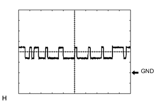
Waveform 1
-
CAN communication signal
Item Content Tester Connection I19-17 (CA2L) - I19-25 (GND) Tool Setting 1 V/DIV., 10 μsec./DIV. Condition Power switch on (IG) Tech Tips
The waveform varies depending on the CAN communication signal.
-
-
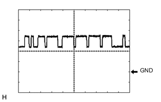
Waveform 2
-
CAN communication signal
Item Content Tester Connection I19-18 (CA1N) - I19-25 (GND) Tool Setting 1 V/DIV., 10 μsec./DIV. Condition Power switch on (IG)
-
-
Waveform 3
-
CAN communication signal
Item Content Tester Connection I19-39 (CA2H) - I19-25 (GND) Tool Setting 1 V/DIV., 10 μsec./DIV. Condition Power switch on (IG) Tech Tips
The waveform varies depending on the CAN communication signal.
-
-
Waveform 4
-
CAN communication signal
Item Content Tester Connection I19-40 (CA1P) - I19-25 (GND) Tool Setting 1 V/DIV., 10 μsec./DIV. Condition Power switch on (IG)
-
-